IEEE AC1A Exciter
Description of the IEEE AC1A Exciter component in Schematic Editor, which represents the field-controlled alternator-rectifier excitation systems designated Type AC1A.
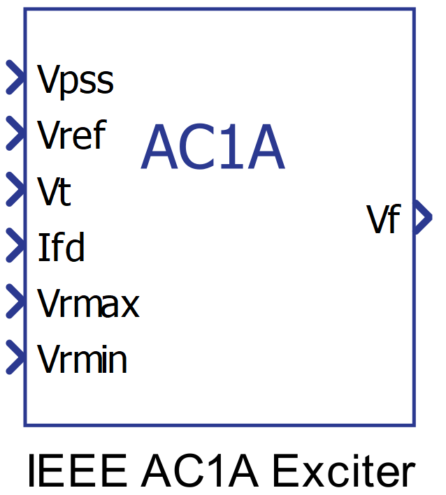
Component Icon
Description
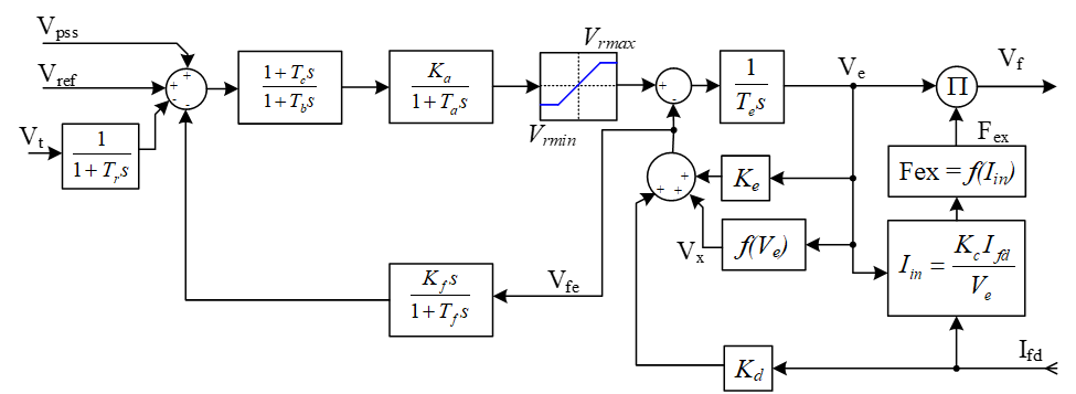
This component represents the field-controlled alternator-rectifier excitation systems designated Type AC1A. These excitation systems consist of an alternator main exciter with non-controlled rectifiers. The exciter does not employ self-excitation, and the voltage regulator power is taken from a source that is not affected by external transients. The diode characteristic in the exciter output imposes a lower limit of zero on the exciter output voltage.
A block diagram of the AC1A exciter is shown below.
Ports
- Vpss (in)
- Connect this input to a power system stabilizer to provide additional
stabilization of power system oscillations.
- Supported types: uint, int and real.
- Vector support: no.
- Connect this input to a power system stabilizer to provide additional
stabilization of power system oscillations.
- Vref (in)
- The desired value, in pu, of the stator terminal voltage.
- Supported types: uint, int and real.
- Vector support: no.
- The desired value, in pu, of the stator terminal voltage.
- Vt (in)
- Output from the terminal voltage transducer and load compensator model
described by this model as standard states.
- Supported types: uint, int and real.
- Vector support: no.
- Output from the terminal voltage transducer and load compensator model
described by this model as standard states.
- Vrmax (in)
- Saturation upper limit of the voltage regulator in pu.
- Supported types: uint, int and real.
- Vector support: no.
- Saturation upper limit of the voltage regulator in pu.
- Vrmin (in)
- Saturation lower limit of the voltage regulator in pu.
- Supported types: uint, int and real.
- Vector support: no.
- Saturation lower limit of the voltage regulator in pu.
- Vf (out)
- Field voltage, in pu, for a Synchronous Machine block
- Supported types: real.
- Vector support: no.
- Field voltage, in pu, for a Synchronous Machine block
Properties
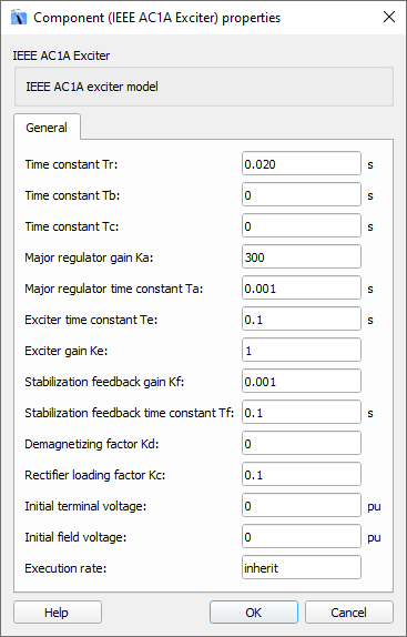
- Time constant Tr
- Type in the terminal voltage transducer time constant. Set to 0 if terminal voltage measurement already accounts for measurement time delay.
- Time constants Tb and Tc
- Type in the time constants Tb and Tc that may be used to model equivalent time constants inherent in the voltage regulator. However, these time constants are frequently small enough to be neglected.
- Major regulator gain Ka and time constant Ta
- Type in the values of the major time constant, Ta, and the gain, Ka, represented by a first-order system associated with the voltage regulator.
- Exciter gain Ke and time constant Te
- Type in the values of the time constant, Te, and the gain, Ke, represented by a first-order system associated with the exciter.
- Stabilization feedback gain Kf and time constant Tf
- Type in the values of the time constant, Tf, and the gain, Kf, represented by a first-order system associated with the stabilization feedback which uses a signal derived from field voltage in order to provide excitation system stabilization.
- Demagnetizing factor Kd
- Type in the demagnetizing factor, which is a function of the exciter alternator reactance.
- Rectifier loading factor Kc
- Type in the rectifier loading factor, which is a gain proportional to the commutating reactance.
- Initial terminal voltage and Initial field voltage
- Type in the initial values of terminal voltage and field voltage, in pu.
- Execution rate
- Type in the desired signal processing execution rate. This value must be compatible with other signal processing components of the same circuit: the value must be a multiple of the fastest execution rate in the circuit. There can be up to four different execution rates. To specify the execution rate, you can use either decimal (e.g. 0.001) or exponential values (e.g. 1e-3) in seconds. Alternatively, you can type in ‘inherit’ in which case the component will be assigned execution rate based on the execution rate of the components it is receiving input from.