IEEE Type 1 Exciter
Description of the IEEE Type 1 Exciter component in Schematic Editor, which provides generic excitation for any synchronous machine and regulates its terminal voltage in generating mode.
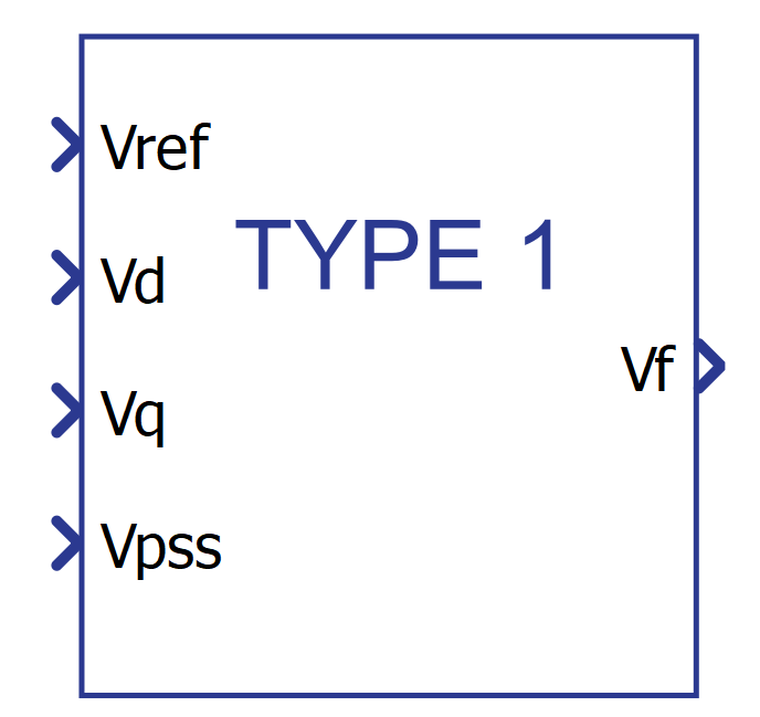
Component icon
Note: This component requires an active Grid Resources functional library license for real-time simulation.
Description
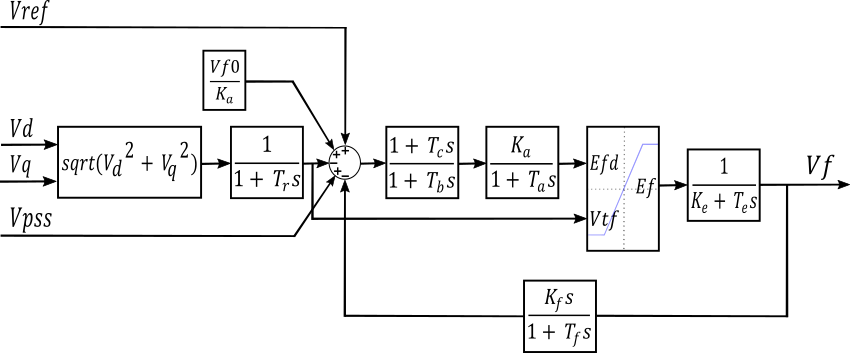
The Type 1 excitation system is representative of the majority of modern systems now in service. It utilizes a DC commutator exciter with a continuously acting voltage regulator, without the exciter's saturation function. A block diagram of the IEEE Type 1 exciter is shown in Figure 2, where the main voltage regulator is represented by constants Ka and Ta and the exciter is represented by constants Ke and Te.
Ports
- Vref (in)
- The desired value of the stator terminal voltage (in pu).
- Supported types: uint, int, and real.
- Vector support: no.
- The desired value of the stator terminal voltage (in pu).
- Vd (in)
- Vd component of terminal voltage (in pu).
- Supported types: uint, int, and real.
- Vector support: no.
- Vd component of terminal voltage (in pu).
- Vq (in)
- Vq component of terminal voltage (in pu).
- Supported types: uint, int, and real.
- Vector support: no.
- Vq component of terminal voltage (in pu).
- Vpss (in)
- Connect this input to a power system stabilizer to provide
additional stabilization of power system oscillations.
- Supported types: uint, int, and real.
- Vector support: no.
- Connect this input to a power system stabilizer to provide
additional stabilization of power system oscillations.
- Vf (out)
- Field voltage for a Synchronous Machine block (in pu).
- Supported types: real.
- Vector support: no.
- Field voltage for a Synchronous Machine block (in pu).
Properties
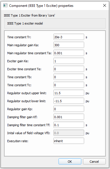
- Time constant Tr
- Type in the terminal voltage transducer time constant.
- Main regulator gain Ka and time constant Ta
- Type in the values of the time constant, Ta, and the gain, Ka, represented by a first-order system associated with the main voltage regulator.
- Exciter gain Ke and time constant Te
- Type in the values of the time constant, Te, and the gain, Ke, represented by a first-order system associated with the exciter.
- Time constants Tb and Tc
- Type in the time constants, Tb, and Tc that may be used to model equivalent time constants inherent in the voltage regulator. However, these time constants are frequently small enough to be neglected.
- Regulator output limits and gain
- Type in the values for the upper Efmax and lower Efmin output limits of the voltage regulator in pu. The upper limit can be constant or variable. If proportional gain Kp is set to 0, upper limit is constant and equal to Efmax. If Kp is set to a positive value, upper limit is equal to the product of rectified stator terminal voltage and Kp.
- Damping filter gain Kf and time constant Tf
- Type in the values of the time constant, Tf, and the gain, Kf, represented by a first-order system associated with the derivative feedback.
- Initial value of field voltage
- Initial value of field voltage (in pu). This property is set to 0 and is currently disabled.
- Execution rate
- Type in the desired signal processing execution rate. This value must be compatible with other signal processing components of the same circuit: the value must be a multiple of the fastest execution rate in the circuit. There can be up to four different execution rates. To specify the execution rate, you can use either decimal (e.g. 0.001) or exponential values (e.g. 1e-3) in seconds. Alternatively, you can type in ‘inherit’ in which case the component will be assigned execution rate based on the execution rate of the components it is receiving input from.