IEEE DC4B Exciter
Description of the IEEE DC4B Exciter component in Schematic Editor, which provides generic excitation for a synchronous machine and regulates its terminal voltage in generating mode.
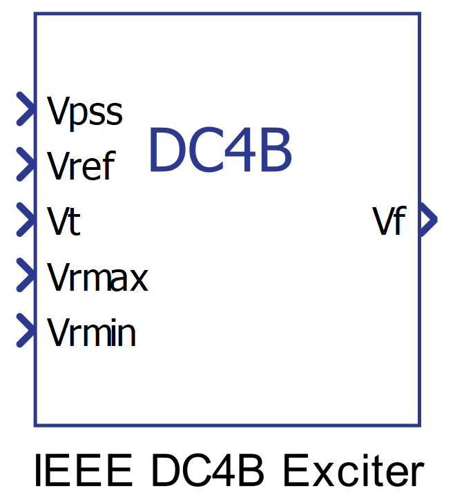
Component Icon
Description
These excitation systems utilize a field-controlled dc commutator exciter with a continuously acting voltage regulator having supplies obtained from the generator or auxiliary bus. This excitation system includes a proportional, integral, and differential (PID) voltage regulator.
The IEEE DC4B is similar to the DC1A except that a PID block replaces the lead-lag network. A block diagram of the system without overexcitation and underexcitation limiters is shown in Figure 2.

The exciter core saturation is not modeled. This is equivalent to setting Vx to 0 in Figure 2.
Ports
- Vpss (in)
- Connect this input to a power system stabilizer to provide additional
stabilization of power system oscillations.
- Supported types: uint, int and real.
- Vector support: no.
- Connect this input to a power system stabilizer to provide additional
stabilization of power system oscillations.
- Vref (in)
- The desired value, in pu, of the stator terminal voltage.
- Supported types: uint, int and real.
- Vector support: no.
- The desired value, in pu, of the stator terminal voltage.
- Vt (in)
- Output from the terminal voltage transducer and load compensator model
described by this model as standard states.
- Supported types: uint, int and real.
- Vector support: no.
- Output from the terminal voltage transducer and load compensator model
described by this model as standard states.
- Vrmax (in)
- Saturation upper limit of the voltage regulator in pu.
- Supported types: uint, int and real.
- Vector support: no.
- Saturation upper limit of the voltage regulator in pu.
- Vrmin (in)
- Saturation lower limit of the voltage regulator in pu.
- Supported types: uint, int and real.
- Vector support: no.
- Saturation lower limit of the voltage regulator in pu.
- Vf (out)
- Field voltage, in pu, for a Synchronous Machine block
- Supported types: real.
- Vector support: no.
- Field voltage, in pu, for a Synchronous Machine block
Properties
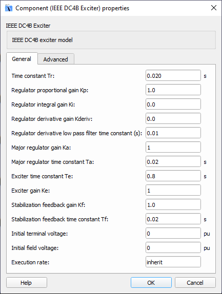
- Time constant Tr
- Type in the terminal voltage transducer time constant. Set to 0 if terminal voltage measurement already accounts for measurement time delay.
- Regulator proportional gain Kp, integral gain Ki, and derivative gain
Kderiv
- Type in the values of the proportional, integral, and derivative gains used for compensation of the exciter system according to the IEEE standard.
- Regulator derivative low pass filter time constant
- Type in the value of the time constant of the low-pass filter of the derivative parcel of the PID regulator.
- Major regulator gain Ka and time constant Ta
- Type in the values of the major time constant, Ta, and the gain, Ka, represented by a first-order system associated with the voltage regulator.
- Exciter gain Ke and time constant Te
- Type in the values of the time constant, Te, and the gain, Ke, represented by a first-order system associated with the exciter.
- Stabilization feedback gain Kf and time constant Tf
- Type in the values of the time constant, Tf, and the gain, Kf, represented by a first-order system associated with the stabilization feedback which uses a signal derived from field voltage in order to provide excitation system stabilization.
- Initial terminal voltage and Initial field voltage
- Type in the initial values of terminal voltage and field voltage, in pu.
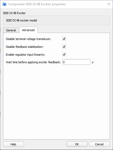
- Disable terminal voltage transducer
- Select this property for disabling the transducer for terminal voltage.
- Disable feedback stabilization
- Select this property for disabling the loop for feedback stabilization.
- Enable regulator input linearity
- Select this property for enabling the linearity of the regulator input.
- Wait time before applying exciter feedback
- Type in the simulation time (in seconds) for applying the exciter feedback.
- Execution rate
- Type in the desired signal processing execution rate. This value must be compatible with other signal processing components of the same circuit: the value must be a multiple of the fastest execution rate in the circuit. There can be up to four different execution rates. To specify the execution rate, you can use either decimal (e.g. 0.001) or exponential values (e.g. 1e-3) in seconds. Alternatively, you can type in ‘inherit’ in which case the component will be assigned execution rate based on the execution rate of the components it is receiving input from.