IEEE ST1A Exciter
Description of the IEEE ST1A Exciter component in Schematic Editor, which represents systems in which the excitation power is supplied through a transformer from the generator terminals and is regulated by a controlled rectifier.
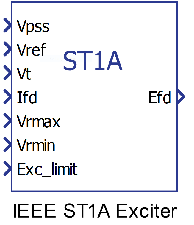
Component Icon
Description
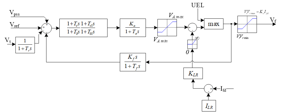
This block represents systems in which excitation power is supplied through a transformer from the generator terminals and is regulated by a controlled rectifier. The maximum exciter voltage available from such systems is directly related to the generator terminal voltage.
In this type of system, the inherent exciter time constants are very small, and exciter stabilization may not be required. On the other hand, it may be desirable to reduce the transient gain of these systems for other reasons. The model shown is sufficiently versatile to represent transient gain reduction implemented either in the forward path via time constants or in the feedback path by suitable choice of rate feedback parameters. Voltage regulator gain and any inherent excitation system time constant are represented by Ka and Ta, respectively.
The ST1A is part of a class of fast static excitation systems. The exciter power is obtained from the machine terminal voltage via a transformer. A thyristor bridge rectifier controls the field voltage by adjusting the thyristor firing angle. A block diagram without overexcitation limiter shown in figure below where UEL represents an underexcitation limiter input. Transient gain reduction or increase, if desired, can be achieved by properly selecting values of Tc, Tb, Tc1, and Tb1. For example, for transient gain reduction, Tc1 should be less than Tb1 and vice versa for transient gain increase.
Ports
- Vpss (in)
- Connect this input to a power system stabilizer to provide additional
stabilization of power system oscillations.
- Supported types: uint, int and real.
- Vector support: no.
- Connect this input to a power system stabilizer to provide additional
stabilization of power system oscillations.
- Vref (in)
- The desired value, in pu, of the stator terminal voltage.
- Supported types: uint, int and real.
- Vector support: no.
- The desired value, in pu, of the stator terminal voltage.
- Vt (in)
- Output from the terminal voltage transducer and load compensator model
described by this model as standard states.
- Supported types: uint, int and real.
- Vector support: no.
- Output from the terminal voltage transducer and load compensator model
described by this model as standard states.
- Ifd (in)
- Value of the stator field current of the controlled synchronous machine
block in pu.
- Supported types: uint, int and real.
- Vector support: no.
- Value of the stator field current of the controlled synchronous machine
block in pu.
- Vrmax (in)
- Saturation upper limit of the voltage regulator in pu.
- Supported types: uint, int and real.
- Vector support: no.
- Saturation upper limit of the voltage regulator in pu.
- Vrmin (in)
- Saturation lower limit of the voltage regulator in pu.
- Supported types: uint, int and real.
- Vector support: no.
- Saturation lower limit of the voltage regulator in pu.
- Exc_limit (in)
-
- Supported types: uint, int and real.
- Vector support: no.
-
- Efd (out)
- Field voltage, in pu, for a Synchronous Machine block
- Supported types: real.
- Vector support: no.
- Field voltage, in pu, for a Synchronous Machine block
Properties
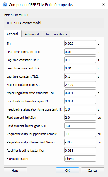
- Time constant Tr
- Type in the terminal voltage transducer time constant. Set to 0 if terminal voltage measurement already accounts for measurement time delay.
- Time constants Tb1 and Tc1
- Type in the time constants Tb1 and Tc1 that may be used to model equivalent time constants inherent in the voltage regulator. However, these time constants are frequently small enough to be neglected.
- Time constants Tb2 and Tc2
- Type in the time constants Tb2 and Tc2 that allow for the possibility of representing transient gain increase, in which case Tc2 is greater that Tb2.
- Major regulator gain Ka and time constant Ta
- Type in the values of the major time constant, Ta, and the gain, Ka, represented by a first-order system associated with the voltage regulator.
- Stabilization feedback gain Kf and time constant Tf
- Type in the values of the time constant, Tf, and the gain, Kf, represented by a first-order system associated with the stabilization feedback which uses a signal derived from field voltage in order to provide excitation system stabilization.
- Field current limit ILr
- Type in the value, in p.u., of the current field limiter employed to protect the generator rotor and exciter.
- Field current limiter gain KLr
- Type in the value of the gain of the field current limiter.
- Regulator output upper limit Vamax and output lower limit Vamin
- Type in the maximum and minimum limits of the regulator output voltage, in pu.
- Rectifier loading factor Kc
- Type in the value of the rectifier loading factor proportional to the commutating reactance
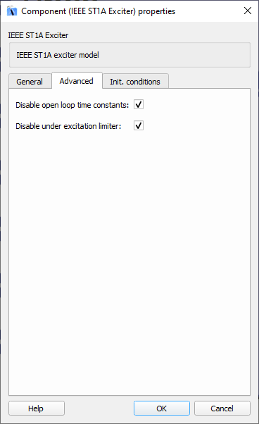
- Disable open loop time constants
- Select this property for disabling the time constants of the open loop.
- Disable under excitation limiter
- Select this property for disabling the limiter for under excitation.
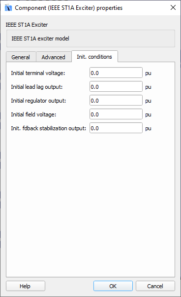
- Initial terminal voltage
- Type in the initial value, in pu, for the terminal voltage.
- Initial lead lag output
- Type in the Initial value, in pu, for the lead lag output.
- Initial regulator output
- Type in the Initial value, in pu, for the regulator output.
- Initial field voltage
- Type in the Initial value, in pu, for the field voltage.
- Init. fdback. Stabilization output
- Type in the Initial value, in pu, for the feedback stabilization output.
- Execution rate
- Type in the desired signal processing execution rate. This value must be compatible with other signal processing components of the same circuit: the value must be a multiple of the fastest execution rate in the circuit. There can be up to four different execution rates. To specify the execution rate, you can use either decimal (e.g. 0.001) or exponential values (e.g. 1e-3) in seconds. Alternatively, you can type in ‘inherit’ in which case the component will be assigned execution rate based on the execution rate of the components it is receiving input from.