IEEE G1 Governor Valve
Description of the IEEE G1 Governor Valve component in Schematic Editor, which provides what is commonly referred to as the Primary Control or Frequency Response of a Steam governor-turbine model.
Component Icon
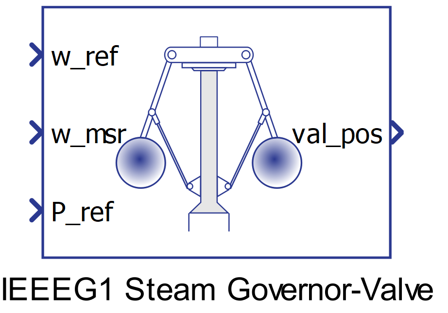
Description
The IEEEG1 steam governor model provides what is commonly referred to as the Primary Control or Frequency Response. It senses changes in the turbine speed (proportional to electrical angular velocity) and adjusts the steam input accordingly. Its response time is generally in the order of seconds. Governor action does not necessarily return frequency to normal after a disturbance, but only stabilizes it.
The governor portion of the model consists of a droop, R with a value typically between 3% and 6% for large interconnected power systems; the time constants T1 and T2 model a lead-lag compensator. The power reference set point is provided by P_ref. The time constant T3 represents the valve servo motor dynamics. The servo speed (valve opening speed) is typically limited to +/-0.1 pu (Uo , Uc ). Limiting of valve position is also provided (Pmax , Pmin ). The dead band unit (Db_Tp2) is a type 2 dead band (offset type) which helps reduce governor regulation effort while preventing speed error discontinuities.
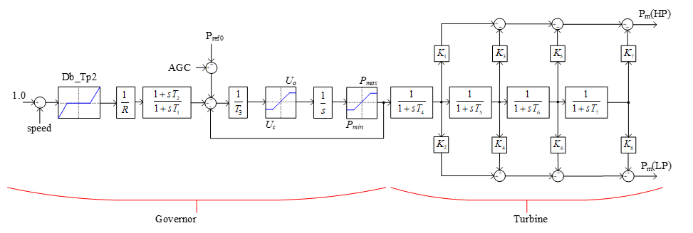
The automatic generation control (AGC) is a control loop composed by a PI compensator and its role is two-fold: to slowly contribute to bringing the grid frequency back to the set-point based on its assigned frequency bias (fb); and to eliminate the area control error (ACE). ACE is the difference between a generation area’s scheduled power production (PMWset ) and its actual power output (Pe ).
.
Ports
- w_ref (in)
- Turbine reference speed.
- Supported types: uint, int and real.
- Vector support: no.
- Turbine reference speed.
- w_msr (in)
- Turbine measured speed .
- Supported types: uint, int and real.
- Vector support: no.
- Turbine measured speed .
- P_ref (in)
- Turbine reference power.
- Supported types: uint, int and real.
- Vector support: no.
- Turbine reference power.
- val_pos (out)
- Position of the servo-valve.
- Supported types: real.
- Vector support: no.
- Position of the servo-valve.
Properties
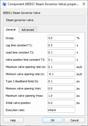
- Droop
- Type in the percentage value for the droop for the governor portion of the model.
- Lag time constant T1 and lead time constant T2
- Type in the values of the time constants T1 and T2 of a lead-lag compensator.
- Valve position time constant T3
- Type in the value T3 that represents the valve servo motor dynamics.
- Maximum valve opening rate Uo and minimum valve opening rate Uc
- Type in the values of the limitation of the servo speed (valve opening speed).
- Type 2 deadbands limits Dz
- Type in the values of the dead band limits. The dead band unit helps reduce governor regulation effort while preventing speed error discontinuities..
- Minimum valve opening Vmin and maximum valve opening Vmax
- Type in the values of the limitation of the servo-valve opening.
- Initial valve position
- Type in the initial position of the valve, in pu.
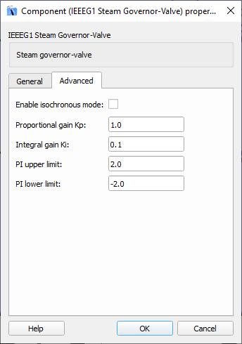
- Enable isochronous mode
- Select this property for enabling isochronous mode control. If set to False, only droop parameters will be used, PI controller will be disabled.
- Proportional gain Kp and integral gain Ki
- Type in the values of the PI control gains. The PI control loop forms the system secondary control loop (also called Outer MW control loop) and has a response time typically on the order of minutes.
- PI upper limit and lower limit
- Type in the values of saturation points of the PI control system (AGC).
- Execution rate
- Type in the desired signal processing execution rate. This value must be compatible with other signal processing components of the same circuit: the value must be a multiple of the fastest execution rate in the circuit. There can be up to four different execution rates. To specify the execution rate, you can use either decimal (e.g. 0.001) or exponential values (e.g. 1e-3) in seconds. Alternatively, you can type in ‘inherit’ in which case the component will be assigned execution rate based on the execution rate of the components it is receiving input from.