IEEE AC8B Exciter
Description of the IEEE AC8B Exciter component in Schematic Editor, which provides an excitation system for a synchronous machine and regulates its terminal voltage in generating mode.
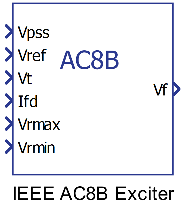
Component Icon
Description
This component provides excitation system for synchronous machine and regulate its terminal voltage in generating mode.
The Type AC8B model can be used to represent static voltage regulators applied to brushless excitation systems. Digitally based voltage regulators feeding dc rotating main exciters can be represented with the AC Type AC8B model with the parameters Kc and Kd set to 0.
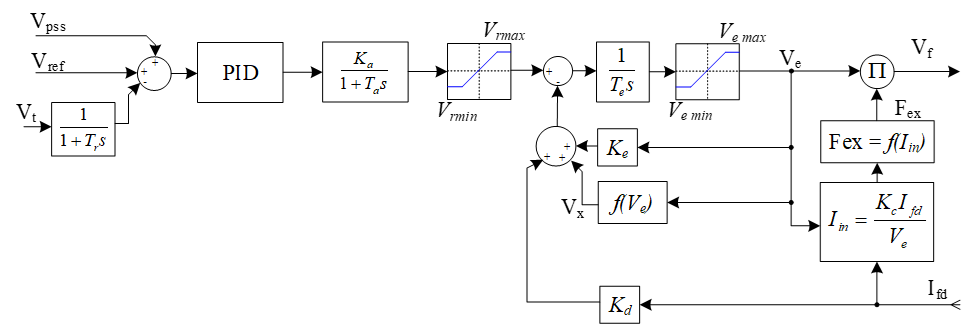
A block diagram of the IEEE AC8B without overexcitation or underexcitation limiters is shown in Figure 2. This exciter is similar to AC1A except that the lead-lag network is replaced by a PID block. Furthermore, an additional limiter is imposed on the brushless excitation system (Te , Ke , Kd , f(Ve), Kc). These excitation system limits are Ve max and Ve min.
Ports
- Vpss (in)
- Connect this input to a power system stabilizer to provide additional
stabilization of power system oscillations.
- Supported types: uint, int and real.
- Vector support: no.
- Connect this input to a power system stabilizer to provide additional
stabilization of power system oscillations.
- Vref (in)
- The desired value, in pu, of the stator terminal voltage.
- Supported types: uint, int and real.
- Vector support: no.
- The desired value, in pu, of the stator terminal voltage.
- Vt (in)
- Output from the terminal voltage transducer and load compensator model
described by this model.
- Supported types: uint, int and real.
- Vector support: no.
- Output from the terminal voltage transducer and load compensator model
described by this model.
- Ifd (in)
- Value of the stator field current of the controlled synchronous machine
block in pu.
- Supported types: uint, int and real.
- Vector support: no.
- Value of the stator field current of the controlled synchronous machine
block in pu.
- Vrmax (in)
- Saturation upper limit of the voltage regulator in pu.
- Supported types: uint, int and real.
- Vector support: no.
- Saturation upper limit of the voltage regulator in pu.
- Vrmin (in)
- Saturation lower limit of the voltage regulator in pu.
- Supported types: uint, int and real.
- Vector support: no.
- Saturation lower limit of the voltage regulator in pu.
- Vf (out)
- Field voltage, in pu, for a Synchronous Machine block
- Supported types: real.
- Vector support: no.
- Field voltage, in pu, for a Synchronous Machine block
Properties
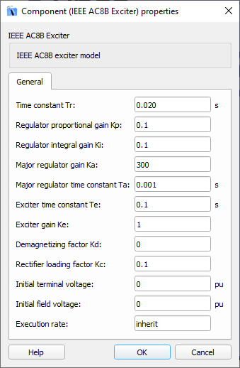
- Time constant Tr
- Type in the terminal voltage transducer time constant. Set to 0 if terminal voltage measurement already accounts for measurement time delay.
- Regulator proportional gain Kp and integral gain Ki
- Type in the values of the proportional and the integral gain used for compensation of the exciter system according to the IEEE standard.
- Major regulator gain Ka and time constant Ta
- Type in the values of the major time constant, Ta, and the gain, Ka, represented by a first-order system associated with the voltage regulator.
- Exciter gain Ke and time constant Te
- Type in the values of the time constant, Te, and the gain, Ke, represented by a first-order system associated with the exciter.
- Demagnetizing factor Kd
- Type in the demagnetizing factor, which is a function of the exciter alternator reactance.
- Rectifier loading factor Kc
- Type in the rectifier loading factor, which is a gain proportional to the commutating reactance.
- Initial terminal voltage and Initial field voltage
- Type in the initial values of terminal voltage and field voltage, in pu.
- Execution rate
- Type in the desired signal processing execution rate. This value must be compatible with other signal processing components of the same circuit: the value must be a multiple of the fastest execution rate in the circuit. There can be up to four different execution rates. To specify the execution rate, you can use either decimal (e.g. 0.001) or exponential values (e.g. 1e-3) in seconds. Alternatively, you can type in ‘inherit’ in which case the component will be assigned execution rate based on the execution rate of the components it is receiving input from.