IEEE G1 Steam Turbine
Description of the IEEE G1 Steam Turbine component in Schematic Editor, a four-stage cross-compound steam turbine model.
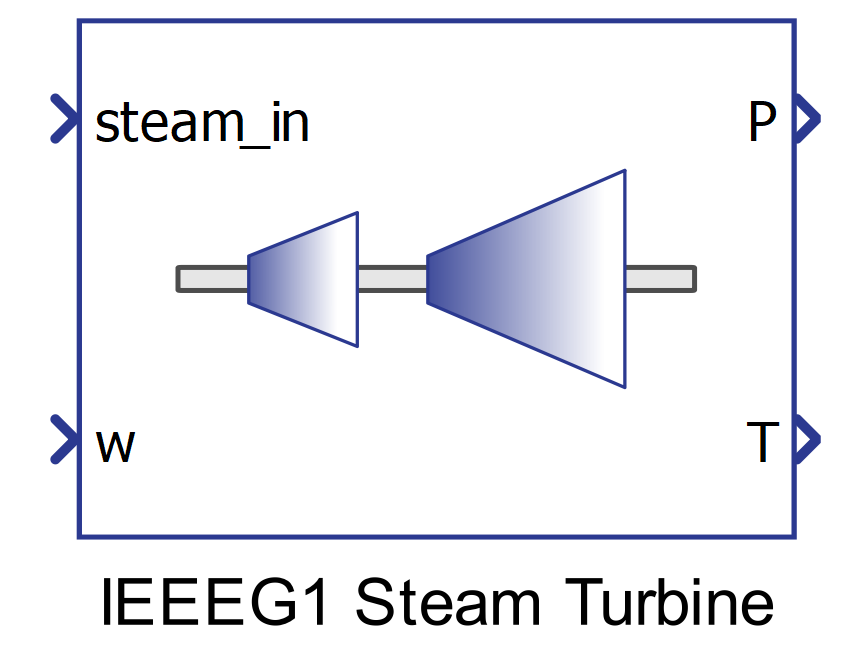
Component Icon

Description
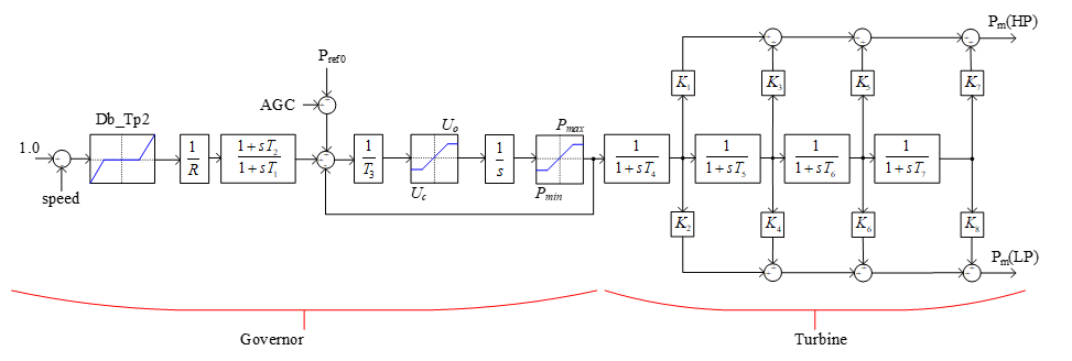
The IEEEG1 steam turbine model consists of a four-stage cross-compound steam turbine where the dynamics of the re-heater stages are captured in the time constants T4 – T7 . The outputs P and T represent the mechanical power output and the mechanical torque respectively.
The IEEE G1 Steam Turbine model complements the steam governor model.

Ports
- steam_in (in)
- Steam input of the turbine
- Supported types: uint, int and real
- Vector support: no
- Steam input of the turbine
- w (in)
- Mechanical speed
- Supported types: uint, int and real
- Vector support: no
- Mechanical speed
- P (out)
- Mechanical power output
- Supported types: real
- Vector support: no
- Mechanical power output
- T (out)
- Mechanical torque output
- Supported types: real
- Vector support: no
- Mechanical torque output
Properties
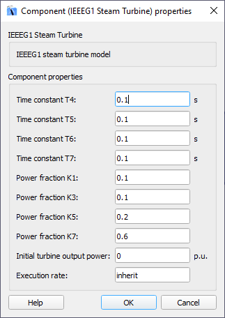
- Time constants T4, T5, T6, T7
- Type in the values of the Time constants that represent the dynamics of the re-heater stages of the turbine
- Power fraction K1, K3, K5, K7
- Type in values of the gains related to the re-heater stages of the turbine that compose the output mechanical power
- Initial turbine output power
- Type in the initial value for the output power
- Execution rate
- Type in the desired signal processing execution rate. This value must be compatible with other signal processing components of the same circuit: the value must be a multiple of the fastest execution rate in the circuit. There can be up to four different execution rates. To specify the execution rate, you can use either decimal (e.g. 0.001) or exponential values (e.g. 1e-3) in seconds. Alternatively, you can type in ‘inherit’ in which case the component will be assigned execution rate based on the execution rate of the components it is receiving input from.
