Accumulator/Integrator
Description of the Accumulator/Integrator components in Schematic Editor, which outputs accumulated/integrated value of an input signal .
Component Icon
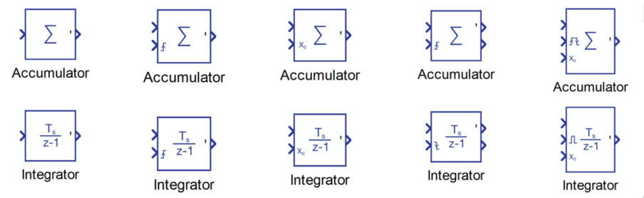
Description
Accumulator and Integrator components differ only in the calculation of the output signal value. Everything else described in this section is the same for these two components.
Accumulator component accumulates the value of an input signal. Accumulator state starts from the initial value and increases by input value each simulation step.
out value = current state + in value
The Integrator component integrates the value of the input signal. Integrator state starts from the initial value and increases by input value multiplied by the component’s execution rate at each simulation step
out value = current state + in value * execution rate
Initial value
The initial value, or initial condition, specifies the Accumulators/Integrators state starting value. The initial value can be specified either internally (through Initial value property) or externally (through the dedicated terminal on the component, labeled with X0).
The initial value applies when the simulation is started and also when the reset signal is active.
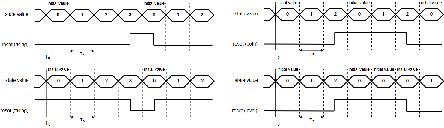
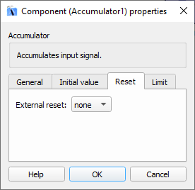
Reset
Accumulator/Integrator state can be externally reset using signals connected to the Reset terminal. Accumulator/Integrator state is reset to the Initial value.
- none - component doesn't support reset
- Rising edge - the state is reset if the rising edge is detected on reset signal (Figure 3, top left)
- Falling edge - the state is reset if the falling edge is detected on reset signal (Figure 3, bottom left)
- Either edge - the state is reset if either the rising or the falling edge is detected on reset signal (Figure 3, top right)
- Level - the state value remains the same as the initial value as long as the reset signal is not 0 (zero) (Figure 3, bottom right)
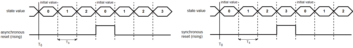
- Asynchronous – the state will reset in the same cycle when the reset signal becomes active
- Synchronous – the state will reset in the next simulation cycle
The difference between two reset types is illustrated on the figure below
State port
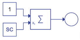
The main functionality of the state port is to break the algebraic loop when an asynchronous reset is used and Accumulator/Integrator output is used to determine the reset signal. If the Show state port property is enabled, a new state output terminal will be created on the component.
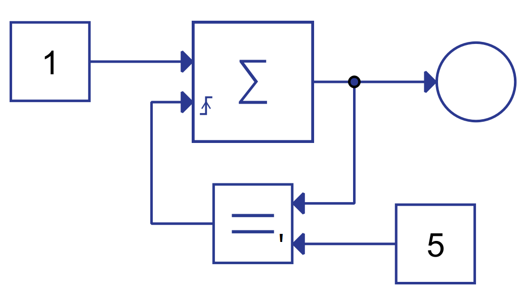
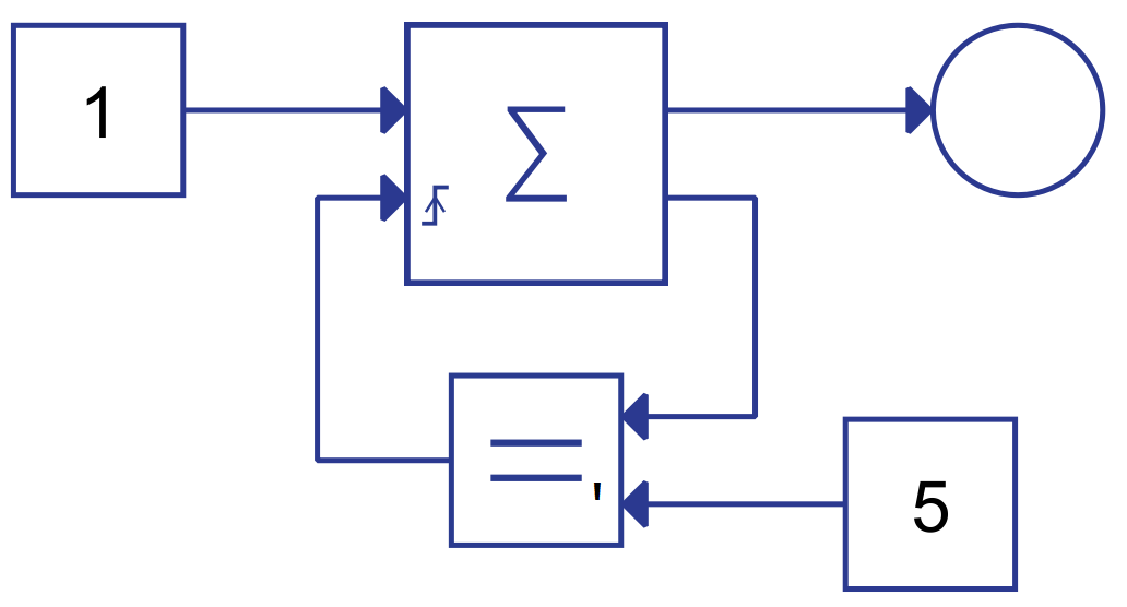
Let us consider the example in Figure 5. The Accumulator component will count to 5 and then reset to 0. If the asynchronous reset is used, the output of the Accumulator depends on the value of the reset signal, and on the other hand, the reset signal depends on the value of the Accumulator's output. This forms an algebraic loop that cannot be solved. To break this loop, the state output must be used as illustrated in Figure 6. Because the asynchronous reset is used, the state of the Accumulator will be reset immediately when the state value reaches 5, and the Accumulator output will be: 0, 1, 2, 3, 4, 0, 1, 2, 3, 4, 0, 1...
The example from Figure 5 would be correct if the synchronous reset type was defined instead of the asynchronous type. In that case, the output of the Accumulator could be calculated regardless of the reset signal in that cycle, and the algebraic loop would not exist. The state would be reset in the next cycle. The output of the Accumulator would be: 0, 1, 2, 3, 4, 5, 0, 1, 2, 3, 4, 5, 0, 1…
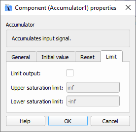
Output limitation
The Output limitation is used to limit the value of the Accumulator/Integrator output. Both upper and lower saturation limits can be defined if the Limit output property is enabled. Values inf and -inf define that there is no upper and/or lower limit.
Terminals
- In (in)
- Supported types: uint, int, real
- Vector support: yes
- Reset (in)
- Supported types: uint, int, real
- Vector support: yes
- Dynamically created when the External reset property is defined accordingly
- Initial condition (in)
- Supported types: uint, int, real
- Vector support: yes
- Dynamically created when the Initial value source property is defined as external
- Out (out)
- Supported types: uint, int, real
- The Output terminal type is calculated based on the types of In and Initial condition ports. If any of the two types are real, the output type will be real, also, if any of the two types are int, the output will be int, else the output will be uint.
- Vector support: yes
- The Vector length is inherited from the In signal or calculated using property value lengths. If the property is defined as a vector, the output will be a vector of the same length.
- Supported types: uint, int, real
- State (out)
- Supported types: uint, int, real
- Output terminal type is defined using the State port out type property
- Vector support: yes
- Vector length is inherited from the Input signal or calculated using property value lengths. If the property is defined as a vector, the output will be a vector of the same length.
- Supported types: uint, int, real
Properties
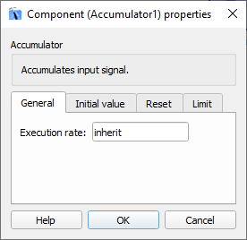
- Execution rate:
- Type in the desired signal processing execution rate. This value must be compatible with other signal processing components of the same circuit: the value must be a multiple of the fastest execution rate in the circuit. There can be up to four different execution rates, but they must all be multiple of the basic simulation timestep. To specify the execution rate, you can use either decimal (e.g. 0.001) or exponential values (e.g. 1e-3) in seconds. Alternatively, you can type in ‘inherit’ in which case the component will be assigned execution rate based on the execution rate of the components it is receiving input from.
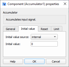
- Initial value source
- Select how the initial value will be defined.
- internal defines that the initial value will be defined through Initial value property.
- external defines that the initial value will be defined through the signal connected to the Initial condition input. The Initial condition input is dynamically created when the external value is selected.
- Select how the initial value will be defined.
- Initial value
- Type in the Initial value of the Accumulator/Integrator state. This value is applied when the simulation is started and when the reset signal is active.
- External reset
- Select how the output state is reset. If the value of this property is not none, an additional terminal is created on the component which allows the user to connect the reset signal that will reset the Accumulators/Integrators state. The State can be reset on the rising edge, the falling edge, both the rising and the falling edges of the reset signal or it can stay in the initial state while the value of reset signal is not 0.
- Reset type
- Select the reset type between:
- asynchronous – state is reset in the same cycle when the reset becomes active
- synchronous – state is reset in the next cycle after the reset becomes active
- Select the reset type between:
- Show state port
- If the property is enabled, an additional terminal will be created on the component that represents the state of the Accumulator/Integrator. This terminal is used primarily to break the algebraic loop that may occur if the output value of the Accumulator/Integrator is used to determine the reset signal.
- State port out type
- Use this property to select the type of signal on the State port.
- Limit output
- If this property is enabled, Upper saturation limit and Lower saturation limit properties are used to limit the output of the Accumulator/Integrator component.
- Upper saturation limit
- Type in the upper limit of the Accumulator/Integrator output.
- Lower saturation limit
- Type in the lower limit of the Accumulator/Integrator output.