Integrator Rollover
Description of the Integrator Rollover component in Schematic Editor, which outputs the integrated value of an input signal.
Component Icon

Description
The Integrator Rollover component integrates the value of the input signal. Integrator state starts from the initial value and increases by input value multiplied by the component’s execution rate at each simulation step
out value = current state + in value * execution rate.
Output rolls over after the specified value.
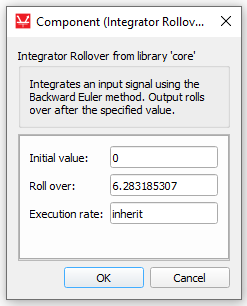
Initial value
The initial value, or initial condition, specifies the Integrator Rollover state starting value.
The initial value applies when the simulation is started and also when the specified value for roll over is reached.
Terminals
- In (in)
- Supported types: uint, int, real
- Vector support: no
- Out (out)
- Supported types: uint, int, real
- Vector support: no
Properties
- Initial value
- Type in the Initial value of the Integrator Rollover state. This value is applied when the simulation is started and when the roll over value is reached.
- Roll over:
- Value after which the output rolls over.
- Execution rate:
- Type in the desired signal processing execution rate. This value must be compatible with other signal processing components of the same circuit: the value must be a multiple of the fastest execution rate in the circuit. There can be up to four different execution rates. To specify the execution rate, you can use either decimal (e.g. 0.001) or exponential values (e.g. 1e-3) in seconds. Alternatively, you can type in ‘inherit’ in which case the component will be assigned execution rate based on the execution rate of the components it is receiving input from.