Delay
Description of the Delay component in Schematic Editor, which outputs the input signal after a delay of N sample periods.
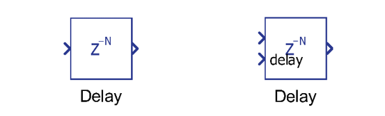
Component Icon
Description
The Delay component outputs the input signal after a delay of N sample periods.
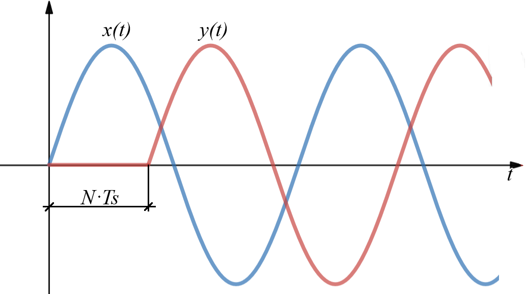
The output signal of the Delay component can be represented by the following mathematical equation, where Ts is the execution rate and N is the desired delay to be applied to the input signal:
Figure 2 illustrates the behavior of the Delay component.
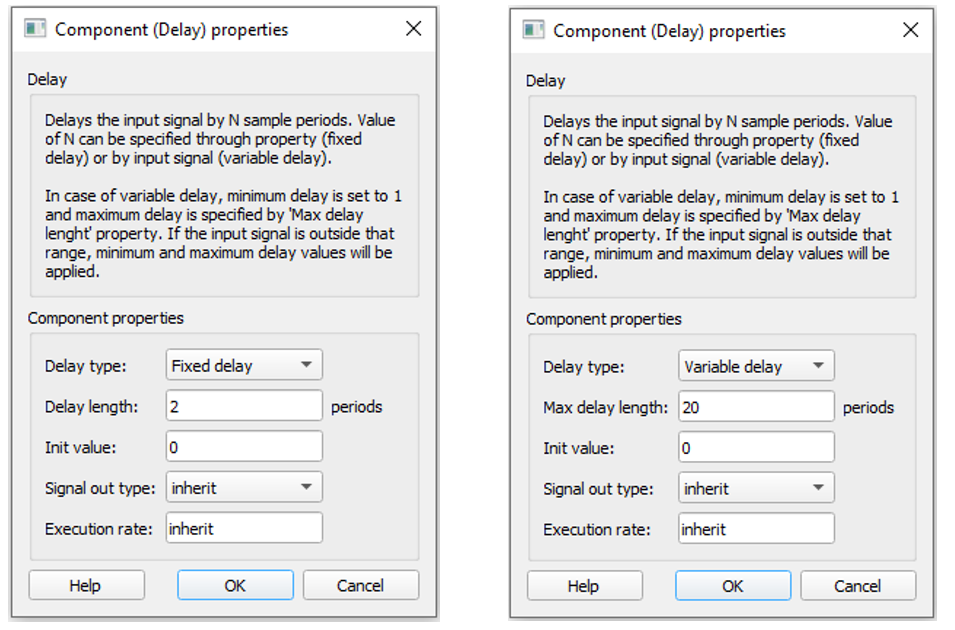
The value of N can be specified through the property (fixed delay) or by the input signal (variable delay).
In case of variable delay, the minimum delay is set to 1 and the maximum delay is specified by the Max delay length property. If the input signal is outside that range, the minimum and maximum delay values will be applied.
Ports
- Input (in)
- Original input signal.
- Supported types: uint, int and real.
- Vector support: yes.
- Original input signal.
- Delay (in)
- External length of delay to be applied to the input signal. Its minimum
value is 1 and the maximum value is defined by the Max delay
length property.
- Supported types: uint, int and real.
- Vector support: yes.
- Dynamically created when the Delay type property is set to Variable delay
- External length of delay to be applied to the input signal. Its minimum
value is 1 and the maximum value is defined by the Max delay
length property.
- Output (out)
- Delayed signal, which is the input signal delayed by N sample
periods.
- Supported types: uint, int and real.
- The output type is defined by the Signal out type property.
- Vector support: yes.
- The vector length is inherited from the input signal or calculated using property value lengths. If the property is defined as a vector, the output will be a vector of the same length.
- Supported types: uint, int and real.
- Delayed signal, which is the input signal delayed by N sample
periods.
Properties
- Delay type
- Select the delay type. If Fixed delay is selected, the input signal will be delayed by Delay length sample steps. If Variable delay is selected, the input signal determines the delay value
- Delay length
- Type in the length of the delay that will be applied to the input signal. This property is available for Fixed delay operation.
- Max delay length
- Type in the length of the maximum delay that can be applied to the input signal. This property is available for Variable delay operation.
- Initial value
- Type in the initial value of the output at the beginning of the simulation
- Signal out type
- Select output signal type. It can be set as “real”, “int”, “uint”, or “inherit”. If "inherit" is selected, output signal will have the same type as input signal.
- Execution rate
- Type in the desired signal processing execution rate. This value must be compatible with other signal processing components of the same circuit: the value must be a multiple of the fastest execution rate in the circuit. There can be up to four different execution rates. To specify the execution rate, you can use either decimal (e.g. 0.001) or exponential values (e.g. 1e-3) in seconds. Alternatively, you can type in ‘inherit’ in which case the component will be assigned execution rate based on the execution rate of the components it is receiving input from.