Unit Delay
Description of the Unit Delay component in Schematic Editor, which delays the input signal by one sample period.
Component Icon
Description
Unit delay component delays the input signal by one sample period.
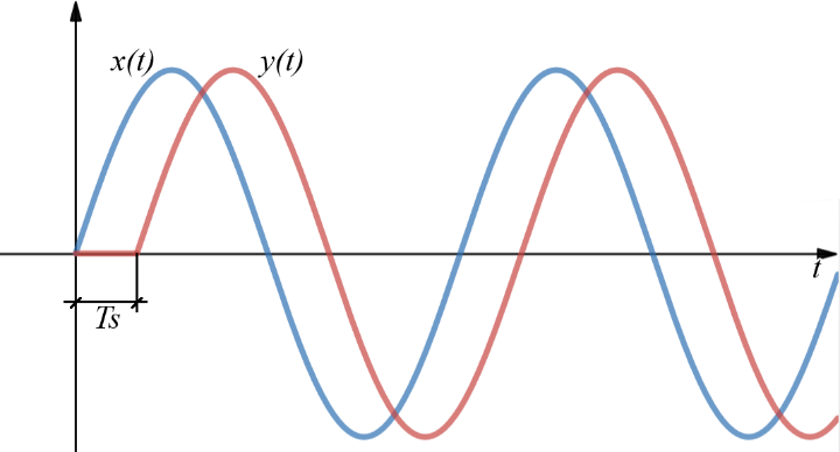
The output signal of the unit delay component can be represented by the following mathematical equation:
y(t) = x (t - Ts)
where Ts is the execution rate. Figure 2 illustrates the behavior of the unit delay component.
Ports
- Input (in)
- Original input signal.
- Supported types: uint, int and real.
- Vector support: yes.
- Original input signal.
- Output (out)
- Input signal delayed by one sample period.
- Supported types: uint, int and real.
- The output type is defined by Signal out type property
- Vector support: yes.
- The vector length is inherited from the input signal or calculated using initial value property value lengths. If the property is defined as a vector and the input is a scalar, the output will be a vector of the same length as the initial value property.
- Supported types: uint, int and real.
- Input signal delayed by one sample period.
Properties
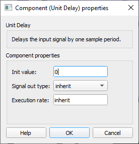
- Initial value
- Type in the initial value set on the output signal at the beginning of the simulation.
- Signal out type
- Select the output signal type. It can be “real”, “int”, “uint”, or “inherit”.
- Execution rate
- Type in the desired signal processing execution rate. This value must be compatible with other signal processing components of the same circuit: the value must be a multiple of the fastest execution rate in the circuit. There can be up to four different execution rates. To specify the execution rate, you can use either decimal (e.g. 0.001) or exponential values (e.g. 1e-3) in seconds. Alternatively, you can type in ‘inherit’ in which case the component will be assigned execution rate based on the execution rate of the components it is receiving input from.