Advanced Low-Pass Filter
Description of the Advanced Low-Pass Filter component in Schematic Editor, which implements a discrete low-pass filter, with the possibility to choose the filter order, cutoff frequency, as well as its type (Basic, Butterworth, Chebyshev1, Chebyshev2, Elliptic) and parameters.
Component Icon


Description
The Low-Pass Filter component implements a low-pass filter on the input signal. The cutoff frequency fc can be defined through the Component Properties menu or connected to the Cutoff frequency input of the component.
All the filters are designed to have a maximum magnitude of 1 (0 dB) in the passband.
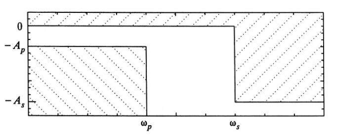
Passband is the range of frequencies over which the magnitude response does not fall below ( ). For a low-pass filter it is the range between 0 and . is called the passband frequency.
Stopband is the range of frequencies over which the magnitude response does not rise above ( ). For a low-pass filter it is the range between 0 and . is called the stopband frequency.
Transition band is the range of frequencies between the passband and the stopband. Roll-off is the term used for the decrease of the magnitude after the passband i.e. it represents the transition band. When comparing roll-offs between filters, it is assumed that the comparison is done for filters with same number of poles.
Cutoff frequency is by definition the frequency in which the magnitude plot has an attenuation of 3 dB. However, this component defines the cutoff frequency for the Chebyshev1 and Elliptic filters as the frequency in which the passband regime is over and after which the magnitude infinitely drops (the official term for this frequency is the passband frequency). Also, the Basic filter represents a filter whose transfer function has all poles within a defined cut-off frequency. Therefore, cutoff frequency is in the -3 dB spot only for the first order of the Basic filter.
Passband attenuation is the width of the passband ripple for the Chebyshev1 and Elliptic filters ( ). Stopband attenuation is the minimum attenuation in the stopband for the Chebyshev2 and Elliptic filters ( ). Basic and Butterworth filters do not have ripples, so they do not have these properties.
where is the radian cutoff frequency obtained from the component, and is the filter order.
The transfer function of the basic filter is:
The transfer function of the Butterworth filter is:
,
where are the poles obtained from:
,
for , is the filter order.
, for
where is the radian cutoff frequency obtained from the component, and is the filter order. is the passband ripple factor obtained from:
.
The transfer function of the Chebyshev1 filter is:
,
where are the poles obtained from:
, ,
for
,
where is the radian cutoff frequency obtained from the component, is the stopband frequency, and is the filter order. is the stopband ripple factor obtained from
,
The transfer function of the Chebyshev2 filter is:
,
are the poles obtained from:
,
where , , for
are the zeros obtained from:
, for
If the order of the filter is odd, the last zero (zero of the highest frequency) is infinity.
is the gain of the transfer function, equal to if the order is even, or if the order is odd.
The magnitude response of the Elliptic filter is:
where is the Jacobian elliptic sine of with modulus , where is the inverse Jacobian elliptic sine of with modulus , is zero if the order is odd and unity if order is even, is the complete elliptic integral of first kind of , and are ripple parameters as same as for the Chebyshev1 and Chebyshev2 filters, and can be obtained from:
,
where is the filter order and is the complete elliptic integral of first kind of .
Ports
- In (in)
- The signal that the filtering should be applied to.
- Supported types: real.
- Vector support: no.
- The signal that the filtering should be applied to.
- Out (out)
- Filtered input signal.
- Supported types: real.
- Vector support: no.
- Filtered input signal.
- Cutoff frequency (fc_input)
- Port enabled when the frequency source of the component is external
(except for the Elliptic filter).
- Supported types: real.
- Vector support: no.
- Port enabled when the frequency source of the component is external
(except for the Elliptic filter).
Properties
- Filter type
- Choose the type of the low-pass filter.
- Filter order
- Type in the order of the low-pass filter.
- Cutoff frequency source
- Choose the source of the cutoff frequency for the low-pass filter. Option "Internal" displays Cutoff frequency property. Option "External" creates a new input port on the component (except for the Elliptic filter).
- Cutoff frequency
- Type in the cutoff frequency of the low-pass filter. Property enabled when the frequency source of the component is internal.
- Passband attenuation
- Type in the passband attenuation of the low-pass filter. It is the attenuation at cut-off frequency for both Chebyshev1 and Elliptic filters.
- Stopband attenuation
- Type in the stopband attenuation of the low-pass filter. It is the attenuation at stopband frequency for both Chebyshev2 and Elliptic filters.
- Execution rate
- Type in the desired signal processing execution rate. This value must be compatible with other signal processing components of the same circuit: the value must be a multiple of the fastest execution rate in the circuit. There can be up to four different execution rates. To specify the execution rate, you can use either decimal (e.g. 0.001) or exponential values (e.g. 1e-3) in seconds. Alternatively, you can type in ‘inherit’ in which case the component will be assigned execution rate based on the execution rate of the components it is receiving input from.
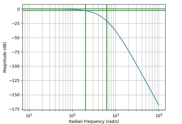
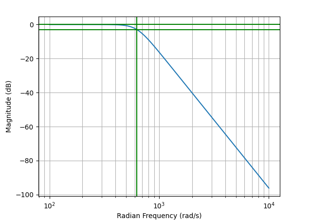
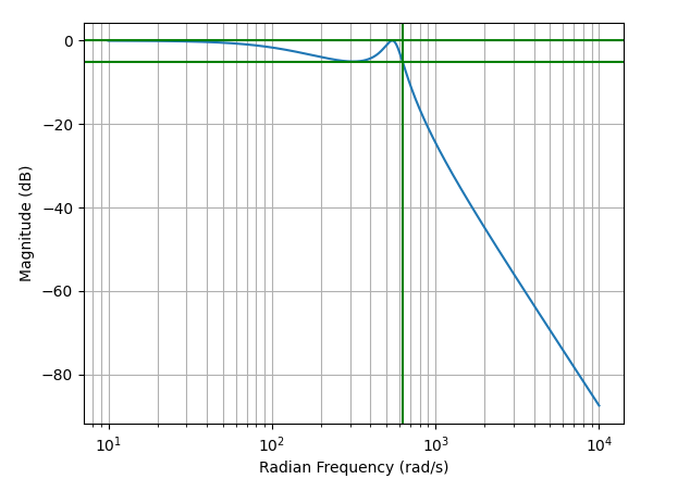
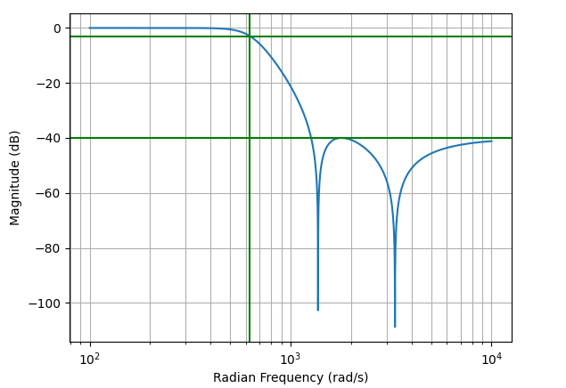
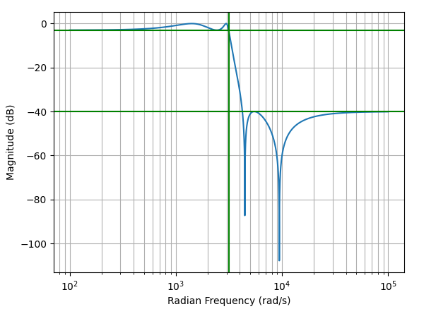
- Bode plot
- Button which displays the magnitude Bode plot of the created filter. If any property is defined through the namespace, or the cutoff frequency is defined externally, a Generic Bode plot with valid parameters will be shown (properties which cannot be evaluated will be substituted with unity or other generic values). Also, a warning will occur in the output console.