Discrete State Space
Description of the Discrete State Space component in Schematic Editor, which implements a discrete state-space system where coefficient matrices can be specified in either the Z-domain or S-domain.
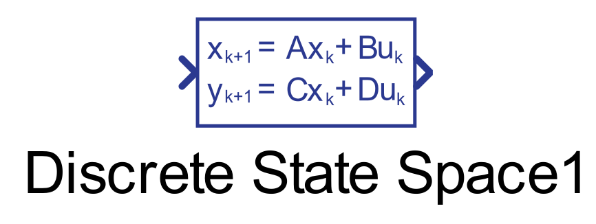
Component Icon
Description
The Discrete State Space component implements a discrete state-space system where coefficient matrices can be specified in either the Z-domain or S-domain.
Continuous state space (S-domain) implements a system described by the following:
where:
- is a state vector, dimensions
- is an input vector, dimensions
- is the output vector, dimensions
- is an matrix, where is the number of states
- is an matrix, where is the number of inputs
- is an matrix, where is the number of outputs
- is an matrix
By transformation of continuous differential equations into discrete difference equations we have a system described by the following:
The discrete state space is obtained from the continuous state space by discretization of coefficient matrices, with one of the following methods:
- Euler method
Calculates an approximate discrete model, based on the appoximation for small timesteps.
- Backward differencing method
- Bilinear method
A method which yields the best frequency-domain match between continuous and discrete systems.The bilinear method is useful if your system has important dynamics that you want to preserve.
- Zero-hold method
This method provides an exact match between the continuous- and discrete-time systems in the time domain for staircase inputs. The method assumes zero-order hold for the input , where is the sample time:
Ports
- Input (in)
- Input signal.
- Supported types: uint, int, and real.
- Vector support: yes.
- The width equals the number of columns in the B and D matrices.
- Input signal.
- Output (out)
- The derivative of the input signal.
- Supported types: uint, int, and real.
- Vector support: yes.
- The vector length is inherited from the input signal.
- The width equals the number of rows in the C and D matrices.
- The derivative of the input signal.
Properties
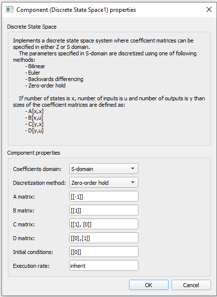
- Coefficients domain
- Select either the S-domain or the Z-domain of coefficient matrices.
- Discretization method
- Select the discretization method of the component if the S-domain is chosen. The available options are: Euler, Backward differencing, Bilinear, or Zero-order hold method.
- A matrix
- Specify the matrix , where is the number of states .
- B matrix
- Specify the matrix , where is the number of states and is the number of inputs.
- C matrix
- Specify the matrix , where is the number of outputs and is the number of states.
- D matrix
- Specify the matrix , where is the number of outputs and is the number of inputs.
- Execution rate
- Type in the desired signal processing execution rate. This value must be compatible with other signal processing components of the same circuit: the value must be a multiple of the fastest execution rate in the circuit. There can be up to four different execution rates. To specify the execution rate, you can use either decimal (e.g. 0.001) or exponential values (e.g. 1e-3) in seconds. Alternatively, you can type in ‘inherit’ in which case the component will be assigned execution rate based on the execution rate of the components it is receiving input from.
References
[1] Åström, K.J. and B. Wittenmark,® Computer-Controlled Systems: Theory and Design, Prentice-Hall, 1990, pp. 48-52.
[2] Franklin, G.F., Powell, D.J., and Workman, M.L.,® Digital Control of Dynamic Systems (3rd Edition), , Prentice-Hall, 1997
[3] T. Laakso, V. Valimaki, "Splitting the Unit Delay",® IEEE Signal Processing Magazine, Vol. 13, No. 1, p.30-60, 1996.