Description of the Low-Pass Filter component in Schematic Editor, which implements a
discrete low-pass filter.
Component Icon
Figure 1. Low-Pass Filter icon
Description
The Low-Pass Filter component implements a first-order low-pass filter on the input signal. The
cutoff frequency fc is defined through the Component Properties menu.
Based on the cutoff frequency, the input-to-output continuous transfer function can be
derived as:
(1),
where ωc
represents the filter cutoff frequency in rad/s. ωc is derived from:
.
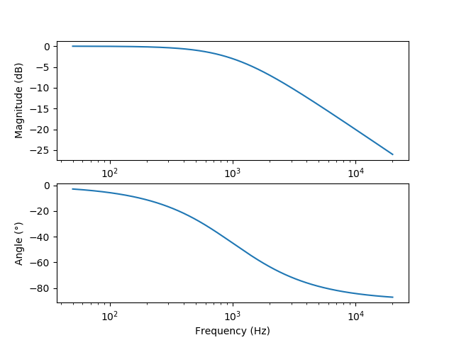
Figure 2 shows the Bode plot for the low-pass filter with a 1kHz cutoff frequency.Figure 2. Bode plot of the low-pass filter
In order to implement the discrete filter, a Euler discretization is applied to (1), which
yields the discrete equation:
,
where .
Ports
In (in)
The signal that the filtering should be applied to.
Supported types: real.
Vector support: yes.
Out (out)
Filtered input signal
Supported types: real.
Vector support: yes.
Properties
Cutoff frequency
Type in the cutoff frequency of the low-pass filter.
To ensure numerical stability of the filter, the maximum cutoff frequency is bounded
such that the filter time constant is three times larger than the execution rate.
Execution rate
Type in the desired signal processing execution rate. This value
must be compatible with other signal processing components of the same circuit: the value must
be a multiple of the fastest execution rate in the circuit. There can be up to four different
execution rates. To specify the execution rate, you can use either decimal (e.g. 0.001) or
exponential values (e.g. 1e-3) in seconds. Alternatively, you can type in ‘inherit’ in which
case the component will be assigned execution rate based on the execution rate of the components
it is receiving input from.
Tunable
Tunable is ignored in
TyphoonSim and changing its value will not affect TyphoonSim
simulation at all.
Enables run-time tuning of the selected
component. This will allow you to change values for cutoff
frequency, during simulation without the need to
recompile the model. Tunable properties are available in HIL
SCADA in Model Explorer.
 Tunable is ignored in
TyphoonSim and changing its value will not affect TyphoonSim
simulation at all.
Tunable is ignored in
TyphoonSim and changing its value will not affect TyphoonSim
simulation at all.