This section describes how to create and use the Virtual signals in the
Capture/Scope widget.
Virtual signals are a special type of signal that can only be used in the Capture mode of
the Capture/Scope widget. Virtual signals are created either by using and transforming
other captured signals or by creating virtual signal data from scratch without using
other signals data. Virtual signal data is specified in the special
transform_function where other captured signals data will be
available as function arguments.
Create, edit, or delete a Virtual signal
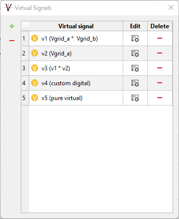
To create a Virtual signal, switch to Capture mode in
the Capture/Scope widget, open the Signal dialog (Figure 1) and click on the
Virtual signals button to open the Virtual signals dialog
(Figure 2)Figure 1. Capture signals list
Figure 2. Virtual signals dialog
In the Virtual Signals dialog you can create a new Virtual signal
( ),
edit () existing one, or delete one or all selected ( ) Virtual signals.
To create a new Virtual signal, click on the button to open the Virtual Signal
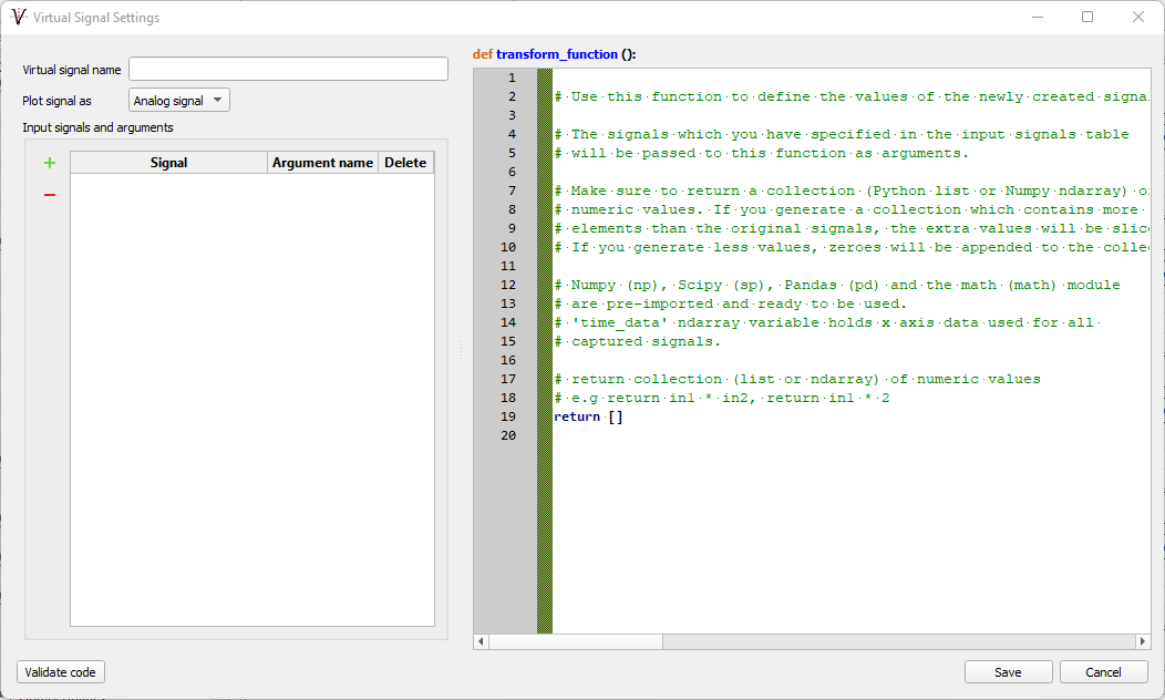
Settings dialog (Figure 2).Figure 3. Virtual Signals Setting dialog
In this dialog you can specify a (unique) Virtual signal name, a list of other captured
signals that will be used as input signals to the transform function, how the Virtual
signal will be plotted, and most importantly specify the Python code inside the transform
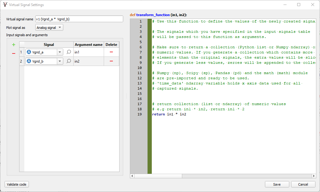
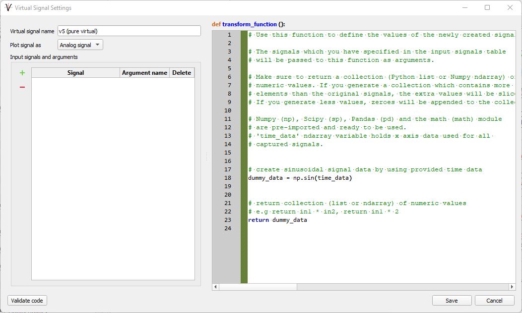
function. With this code you will generate the Virtual signal's data, either by doing
some mathematical transformation on input signals (Figure 5) or generating signal data
from scratch (Figure 6). In
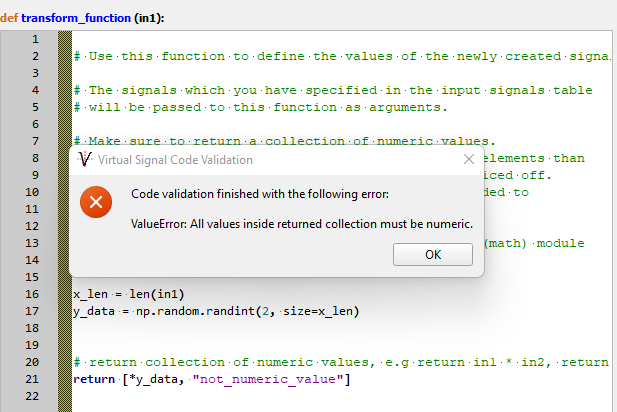
order to check your transformation code you can click on the Validate
code button. This validation will check if there are syntax errors
in the code and if the function return value has the correct type (collection) (Figure 4).Figure 4. Transform function validation
Note: In case input signals are used, any Analog,
Digital or even another Virtual signal can be used as an input signal. In order to
evaluate Virtual signals successfully, all input signals must be added to the Capture
signals list (Figure 1).
Note: For validation, dummy sinusoidal data
(1000 points) will be used for each input signal.
Note: Each input signal is passed to the
transform_function as an argument of the NumPy ndarray
type.
Note: The return value of the
transform_function must be a collection (Python list or
NymPy ndarray) of numbers only.
Note: All created
Virtual signals are saved in the currently opened SCADA Panel (.cus)
file.
Figure 5. Generating Virtual signal data by using other captured signals
Figure 6. Generating Virtual signal data by creating signal data from
scratch
To edit an existing Virtual signal click on the
button to open the Virtual Signal Settings dialog (Figure 5) pre-populated with
the Virtual signal's properties data. You can change the Virtual signal in the same way
you create new one.
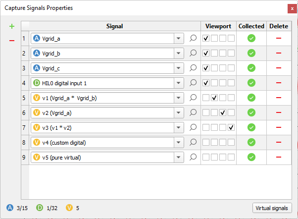
Using Virtual signals
After a Virtual signal is created, it can be selected in the Capture signals
properties dialog.Figure 7. Select created Virtual signals
Note: At least one Analog or Digital signal must be
specified in the Capture Signals Property list. The Capture
process cannot be started if only Virtual signals are used.
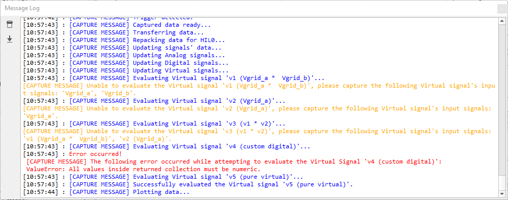
After a Capture cycle is finished and before captured data is plotted, all Virtual signals specified in the Capture Signals
Properties list will be evaluated.
Any errors that occur or warnings that are issues are displayed in the Message Log
console.Figure 8. Virtual signal evaluation errors and warnings
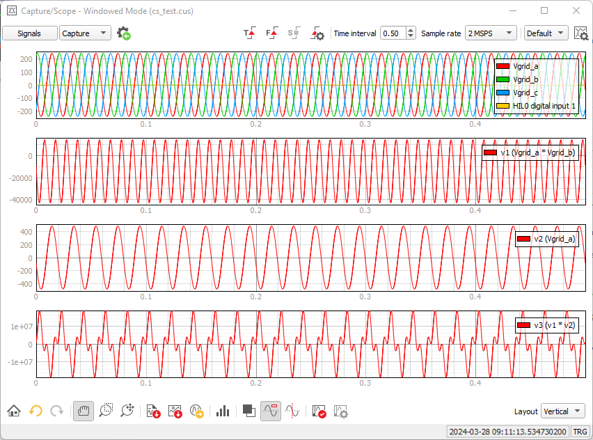
Once all Virtual signals are evaluated, captured Analog/Digital signals and
successfully evaluated Virtual signals will be plotted to the specified
view-ports. Figure 8. Plotted Virtual signals
 ),
edit (
),
edit ( ) existing one, or delete one or all selected (
  ) Virtual signals.