Scope
Description of the Scope functions of the Capture/Scope widget in HIL SCADA
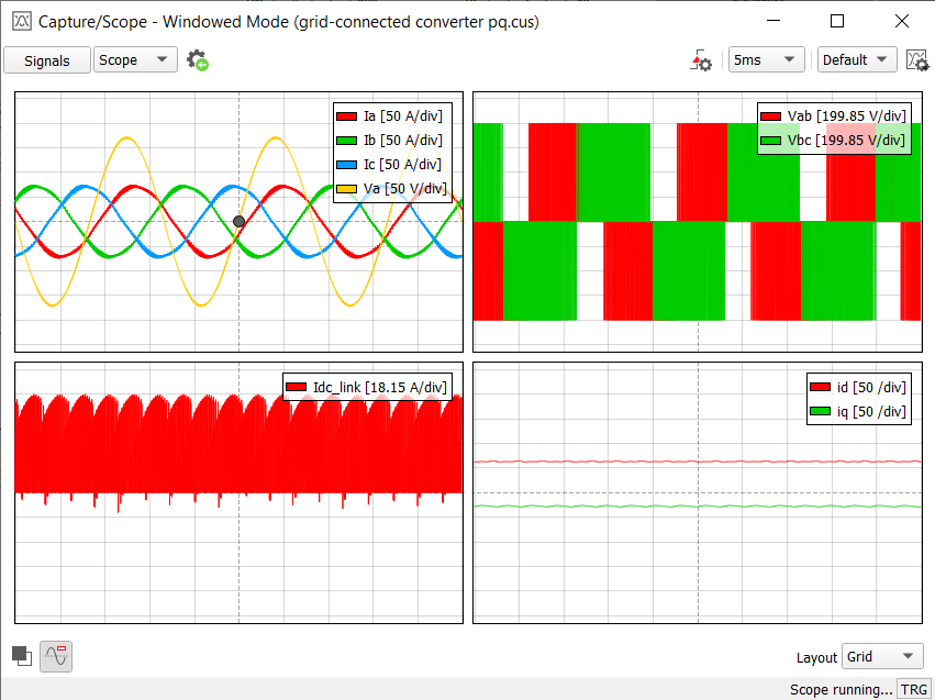
When the Capture/Scope Widget is in the Scope mode (Figure 1), you can use the scope functionality. The observed signals are directly fed to the PC from the connected HIL device.
In the toolbar, you can set the basic scope functionality – time base.
Clicking  opens the
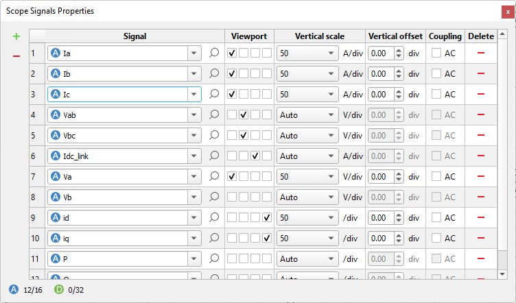
Signals window (Figure 2). This window contains a
dynamic table where you can easily add (
opens the
Signals window (Figure 2). This window contains a
dynamic table where you can easily add ( ) and remove (
 ) analog or digital signals. In the first column, there
is a combo box with all analog and digital signals that exist in the loaded Model. You can select
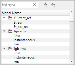
a signal from the combo box or from the tree preview by clicking
) analog or digital signals. In the first column, there
is a combo box with all analog and digital signals that exist in the loaded Model. You can select
a signal from the combo box or from the tree preview by clicking  (Figure 3). Double-clicking on a signal in the
tree selects that signal.
(Figure 3). Double-clicking on a signal in the
tree selects that signal.
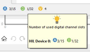
Below the signal table is a small legend that shows the number of used analog and digital signal slots combined for all HIL devices. Hovering the mouse over the legend brings up a small tool-tip (Figure 4) with more information about the used analog and digital slots for each used HIL device in the loaded Model.
You also can assign a signal to the subplot, select vertical scaling (Auto scale is the default option), set the vertical offset, and set the AC coupling for that channel if needed.
Clicking ![]() opens the Scope Trigger Settings window (Figure 5).
opens the Scope Trigger Settings window (Figure 5).
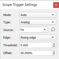
In this window, you can set the triggering mode (Auto, Normal), trigger type, source, edge, threshold and offset.
Also, by dragging the trigger marker in the plotting area you can interactively set offset and threshold of the trigger.
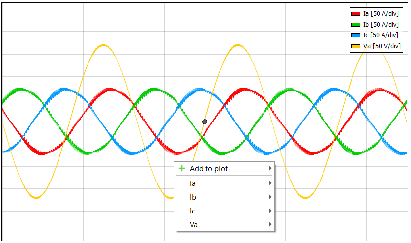
Signal menu (Figure 6) allows you to easily add/remove signals from the plot and/or set them as the trigger source, set their range and offset with one click – all without opening the signal assignment or trigger settings pane. You can open this menu by right-clicking the selected viewport surface.