Signal selection dialog
Overview of how to select specific signal references for a model component
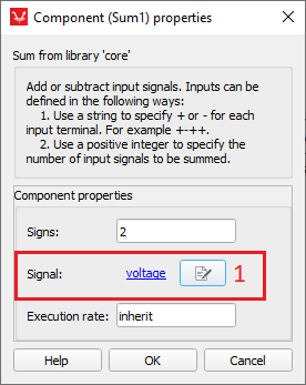
A number of components have properties which are specified as signal references. This means that values of these properties are references to other component's signals. The signal selection dialog is used to set the value of these properties. To display the signal selection dialog options click a button right to the property label (see section numbered by 1 in Figure 1).
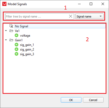
The signal selection dialog has two main entry fields, as shown in Figure 2. The first field, identified by number 1
in the figure, is used to filter the signal tree by one of the
following criteria:
- Signal name.
- Signal type ("analog" or "digital").
- Component type (type of component from where the signal should originate).
When an appropriate signal selection is made, the selection can be confirmed by pressing the OK button. After that, the original component property dialog is again in focus, and the selected signal name is shown to the left (as a label) of the signal selection dialog button. (Figure 3)