Auto-connect component terminals
Description of the behavior of the auto-connection feature
Overview of the Auto-connection feature
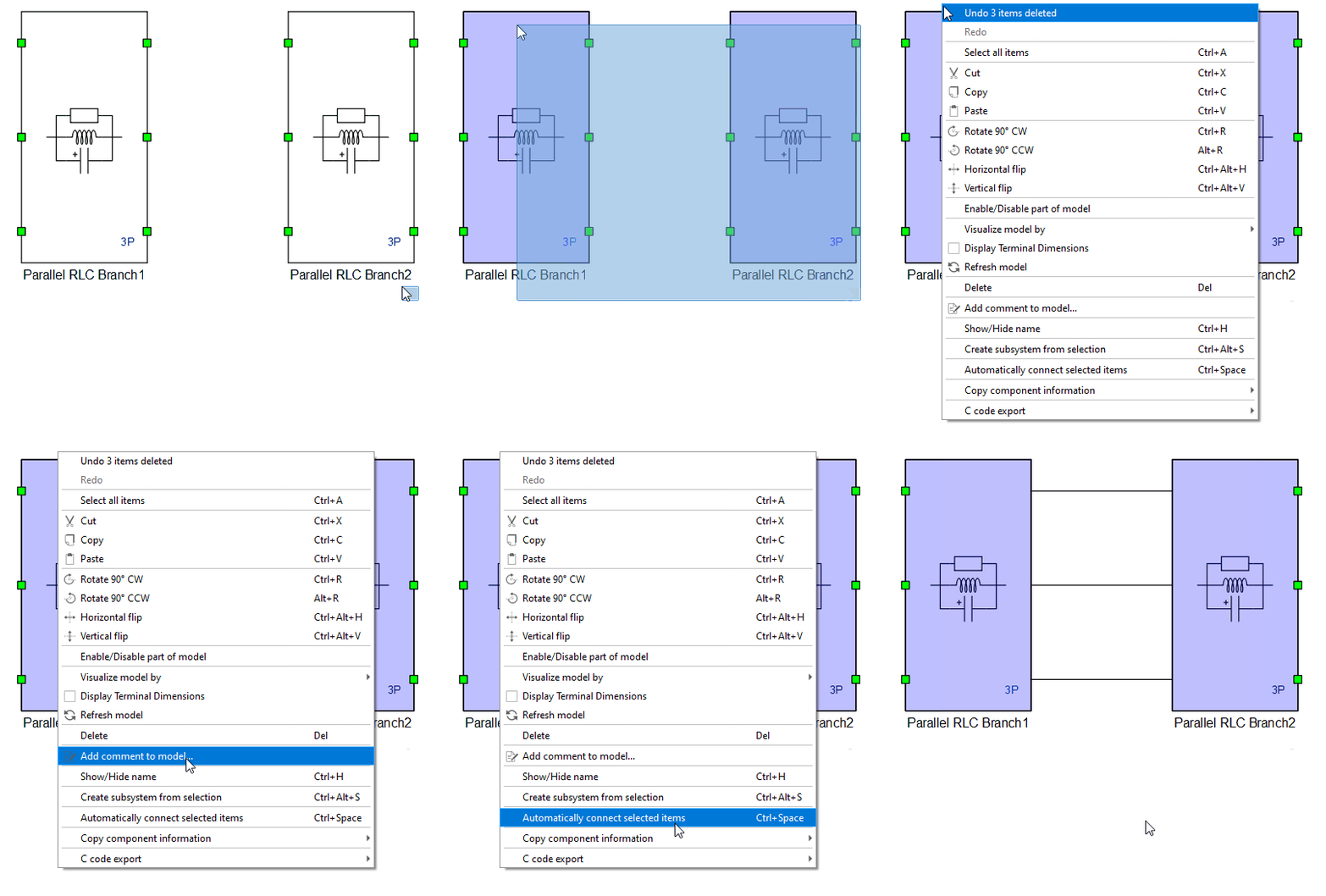
Components can be automatically connected by selecting the desired items of the schematic, and either clicking the Automatically connect selected items option on the right-click menu (Figure 1) or pressing the keyboard shortcut Ctrl + Spacebar. Please keep in mind that each auto-connection step is performed using the keyboard shortcut in the animated examples of this document.
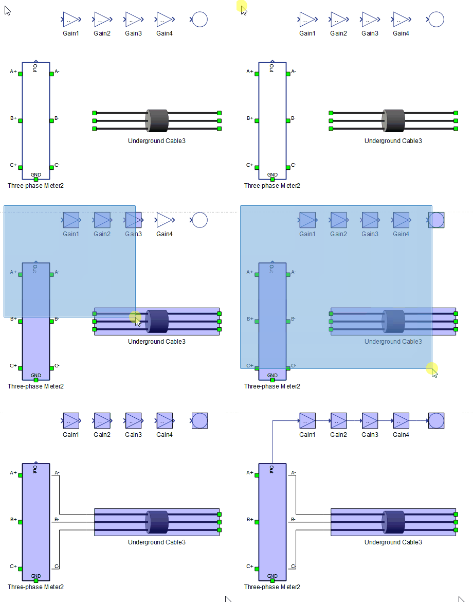
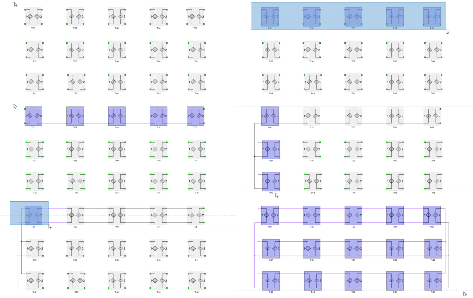
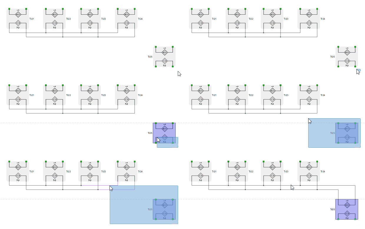
The algorithm will try to determine the intended connection based on type, position and number of unconnected terminals of every selected item. Components that are selected but don't have terminals available for connection are removed from the calculation, which means the command may be reissued several times and new connections made in each step. Furthermore, if the creation of both PE and SP connections is possible with the selected items, PE connections are made first, as shown in Figure 2.
Several types of connections can be performed by selecting items appropriately. Let's go over examples of each type.
Connect exactly two components
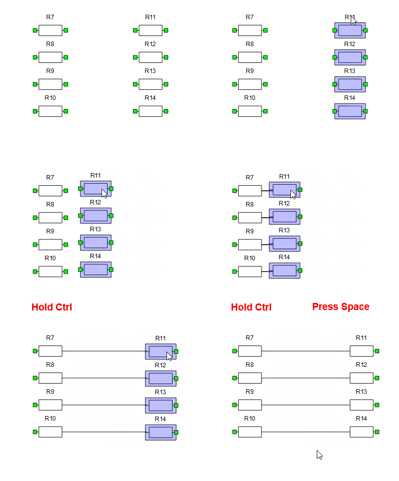
By selecting exactly two components, you can create series or parallel connections between them. The relative position between the components and the position of the unconnected terminals will determine the resulting connections, as can be seen in Figure 3 and Figure 4.
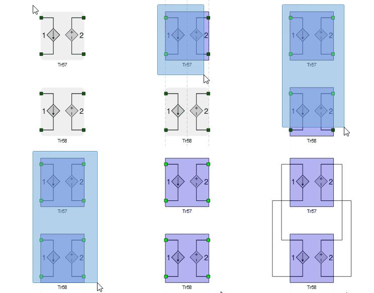
If one component is placed at the side of the other one, and the wires that would leave their terminals have different directions (horizontal / vertical), the connection depicted in Figure 5 is performed.
Multi-component series and parallel connections
Several components may be connected in parallel or series at a time. The algorithm will calculate a score based on the relative position of the components and how many connections will be created. In case equal scores are calculated, preferences are top -> down and left -> right. As a rule of thumb, with a smaller amount of components selected there is a higher chance the algorithm will interpret the intended connections correctly. Figure 2 shows parallel and series connections being created by repeatedly issuing the command.
Connect to existing wires
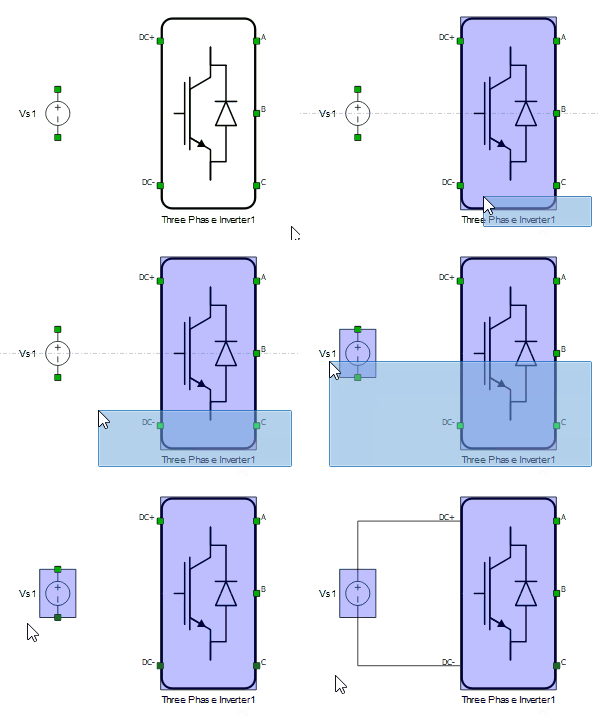
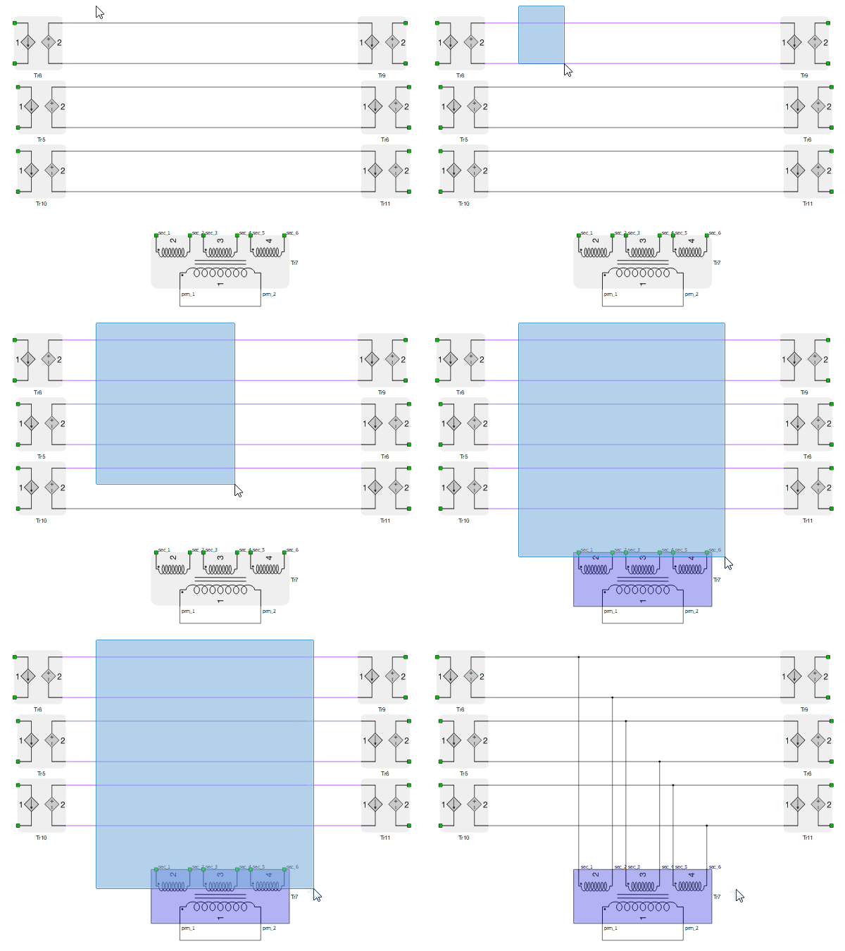
The connection to existing wires allows you to easily connect components such as three-phase loads and filters in parallel. There are a few different behaviors to be aware of. Let's start with Figure 7. Wires that would leave the terminals in a straight line must intersect segments of the selected wires. A junction will be created in the intersection point, and everything reconnected to it. The algorithm will try to match the order of the connections, which is the most common case. If a different order for the connections is needed, it will have to be done manually.
If junctions are selected and positioned in the half-plane space defined by the selected component's side, its terminals will be connected directly to those junctions, as shown in Figure 8.
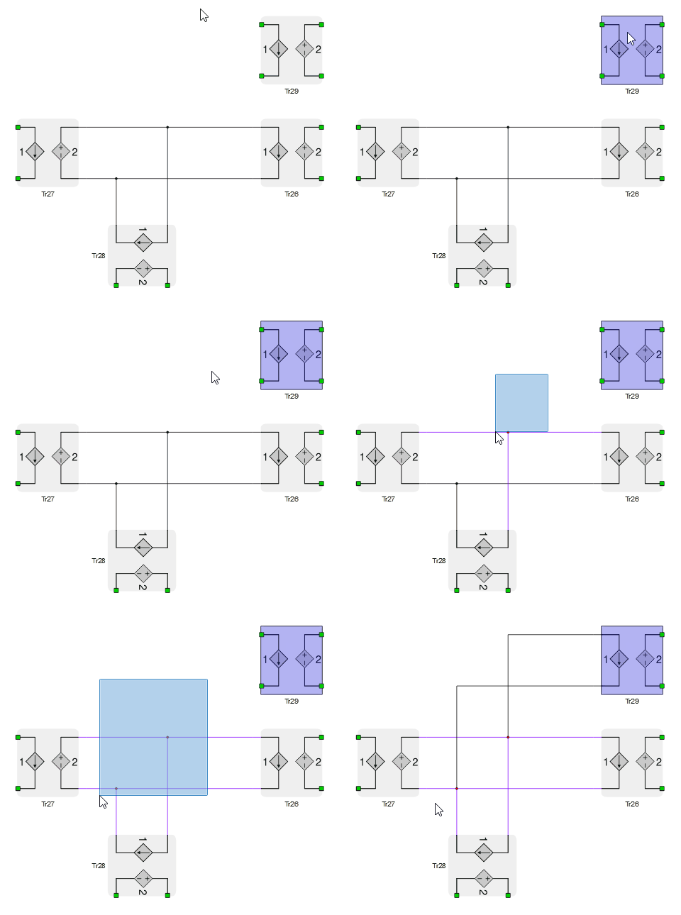
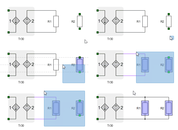
Figure 9 and Figure 10 show two forms that a component can be added to a parallel set. Notice that in the second example R1 is ignored by the algorithm, since all of its terminals are already connected.
Connect one side of a component with many terminals to several components
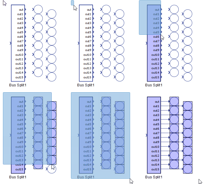
The terminals at the side of a component C may be connected to several other components if they are positioned in the half-plane space defined by the side of the component C and are positioned approximately in parallel to the line that intersects C's terminals. In Figure 8, for example, the right side terminals of Bus Split 1 are intersected by a virtual vertical line, and the Probe components are also approximately positioned vertically in relation to each other.
Short-circuit the terminals on a side of a single component
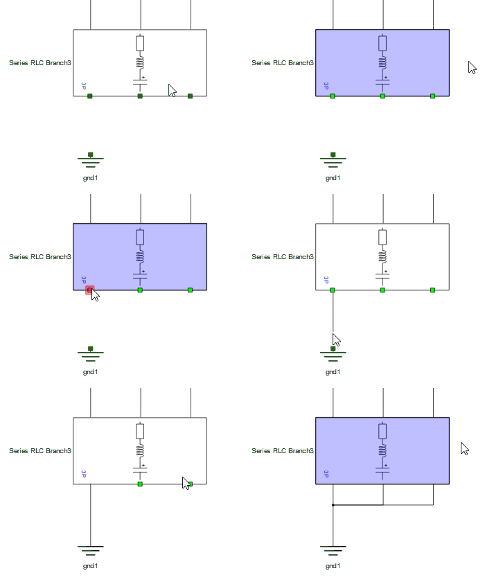
Short-circuiting of the terminals is a useful complement to Connect to existing wires. After adding a load in parallel, for example, the auto-connection command can be repeated to short the opposite side. An odd number of terminals will be shorted at the center, and an even number will be shorted at the first terminal. As Figure 12 shows, if a component terminal is already connected a component, the short-circuit junction will be created at that terminal.
Connect terminals by proximity
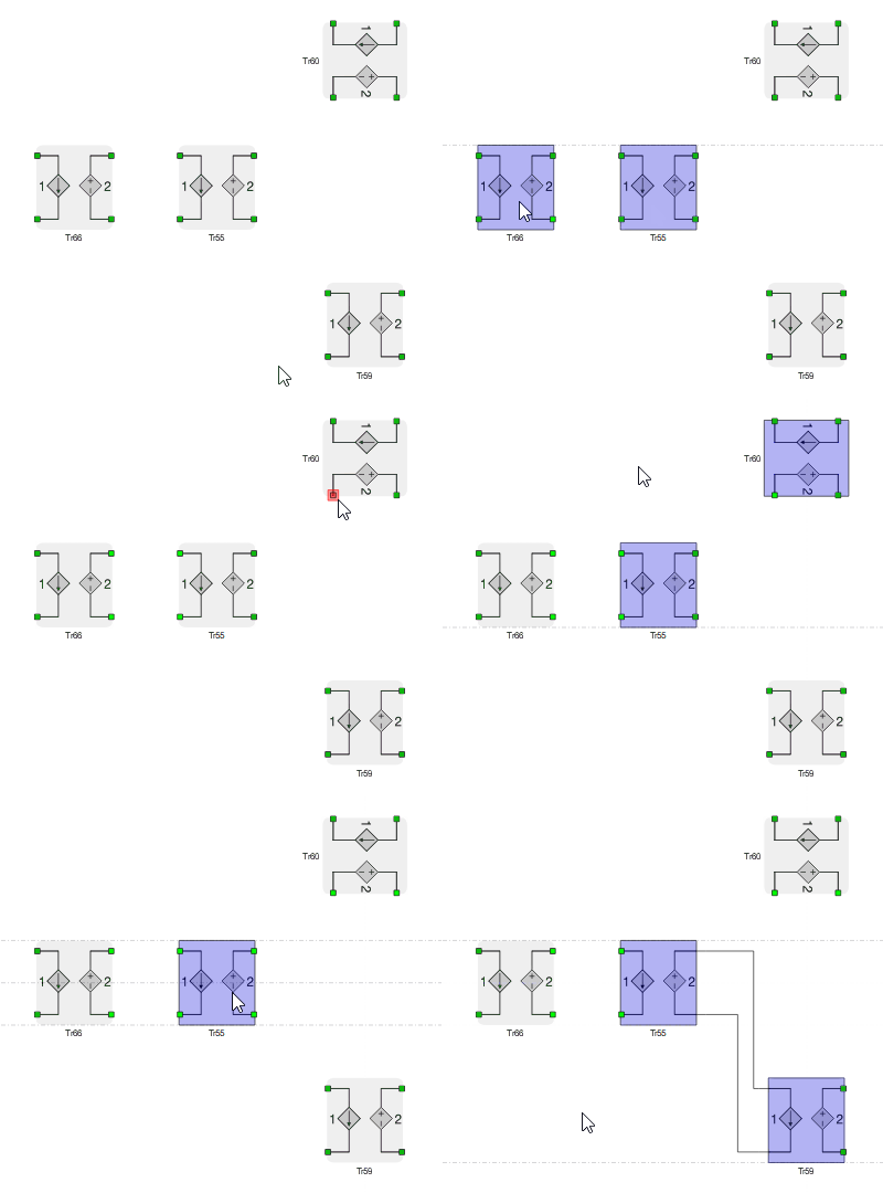
The last connection mode is triggered by holding Ctrl and dragging components. When terminals are colliding and ready for connection, they will turn red. Pressing Spacebar at this point will confirm the connections. This mode is especially useful when some component terminals must be skipped.
