Single-line diagram representation
Describes how the Electric Bus and similar components can be used in conjunction with the Electrical component vectorization feature to create single-line diagrams (SLD).
A single-line diagram is a simplified representation of the circuit schematic where connection lines represent buses with multiple ordered electrical nodes. Buses can be created from a set of standard nodes with the Electrical Bus component, or by vectorizing a component through one of its properties (see Electrical component vectorization).
The Modifying a model to an SLD representation section is an example of how single line diagrams can be constructed.
Modifying a model to an SLD representation
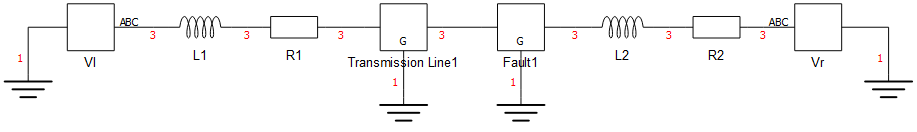
Consider the default, multi-line representation of a model in Figure 1. A single-line version of each multi-phase component can be created by adding the original component to a subsystem, connecting the original terminals to an Electrical Bus, and finally connecting the multi_dim terminal of the Electrical Bus to a Port.

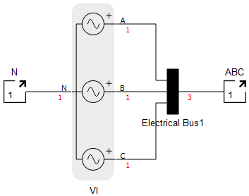
For the Figure 2, the A, B and C terminals of the Three-Phase Source component are connected to an Electrical Bus of bus_size = 3, and its multidimensional terminal is connected to a new port called ABC. The numbers in red are the resulting dimension of the terminals.
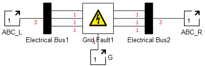
As a second example, the Figure 3 is done by connecting each of the sides of the component to an Electrical Bus and then the multidimensional terminals to new Ports.
The process must be repeated for every multi-phase component. Components that support vectorization - such as resistors and inductors - can be reduced to a single instance and connected to the SLD subsystems. Figure 4 shows the final schematic.