Schematic areas
Description of how to create areas in a schematic to improve visual organization.
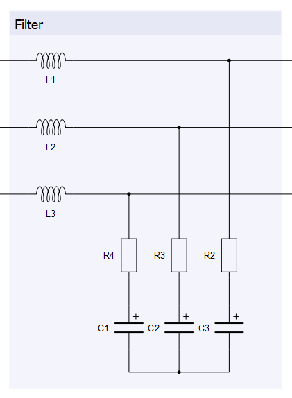
Schematic areas are click-transparent rectangular objects that can be used to visually separate and identify important parts of the model. An example is shown in Figure 1.

Creating schematic areas
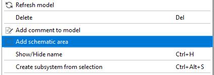
Schematic areas can be created by right-clicking to access the context menu and selecting Add schematic area (Figure 2).

Once clicked, draw a rectangle using the left mouse button (via two clicks or clicking and dragging) to define the area space. The minimum size of the rectangle is visually indicated by a transparent rectangle with dashed lines. After the rectangle is defined, the dialog box shown in Figure 3 appears.

- Title font
- Font color
- Area background color
- Display an outline around the area
Behavior of schematic areas
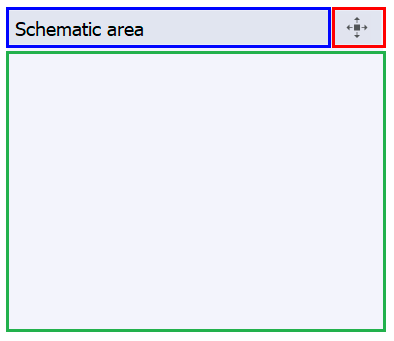
There are three parts in a schematic area, as shown by the colored rectangles in Figure 4. Each part presents a different behavior when clicked with the left mouse button.

The main part (green) is where schematic components are placed. The box is only a visual indicator, so you can work with the components inside it the same as you would work with other components on the main canvas. A single left-click on the title part (in blue) selects the schematic area, and double-clicking it reopens the dialog for editing properties.
You can also move the highlighted schematic area to other parts of the model.
- Dragging the schematic area from the title part simply moves the considered area without moving any elements inside it.
- Dragging the schematic area from the button in the red box (top right of Figure 4), or holding Ctrl while moving from the title box, moves the schematic area together with all elements inside it.