Electrical component vectorization
Describes how specific electrical-type (PE) atomic components can be vectorized.
Electrical component vectorization overview
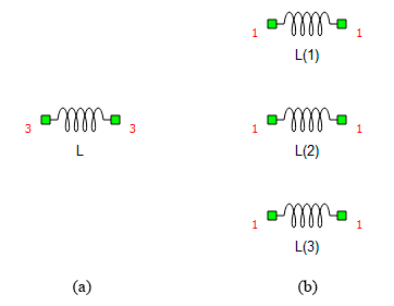
A vectorized component is replaced with N (bus size) instances of the same component on compilation, where N is defined by the bus it is connected to, or by the value of its mask properties. On Figure 1 a vectorized inductor L of size N = 3 is depicted on (a). Once the compilation/validation starts, the inductor is replaced (internally, the schematic is not changed) with 3 separate "scalar" inductors (b) named L(1-3).
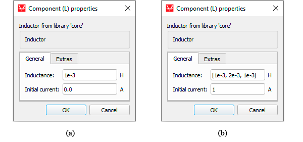
The values of the properties of those new inductors depend on how the original vectorized inductor was defined. Consider the example in Figure 2. All properties in (a) are defined as scalars, while the Inductance property in (b) is defined as a vector (Python list). In case (a), the inductor will be vectorized only if connected to a bus (it also inherits the bus size), and the resulting scalar inductors will have their properties equal to the original inductor. In case (b), the three resulting inductors have their Inductance property set as 1e-3, 2e-3, and 1e-3 (in order), and their Initial current as 1.
Using a list format on property values forces N to be equal to the size of the list, which means a connected bus must be of the same size, as well as lists entered in other properties, otherwise the validation will fail with a dimension mismatch error.
Simple example
Consider the small circuit in Figure 3. The size N=3 is defined on each component as follows:
- Vs1: directly by the Phase property
- IR1 and IR2: the bus size is inherited from connected components
- R1: directly by the Resistance property
- R2: since the Resistance property is a scalar, the size is inherited from connected components
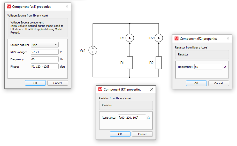
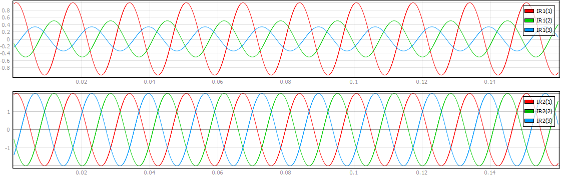
With this parametrization, the Vs1 source becomes effectively a three-phase sinusoidal source. The waveforms of the current measurements, which can be seen in Figure 4, show the phase delay between the currents. The different resistance values on each phase of the R1 resistor produce currents of different amplitudes, while R2 maintains the same value across phases.
List of supported components
These are the PE components that currently support vectorization: