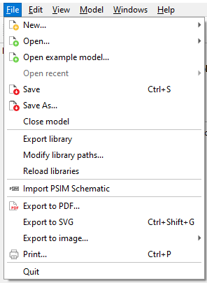
This section describes the menus and toolbar commands available in Schematic Editor
This panel contains the most commonly used commands:
Create a new schematic diagram using the New schematic diagram wizard (Figure 1, Figure 2). The wizard allows you to easily create a
new schematic diagram with hardware properties that match the HIL device in use. Hardware
properties can be set either manually or can be directly obtained from the connected HIL
device (by clicking on the Detect hardware settings button, Figure 1).
If you click on the Device Table button you can get more detailed
information about features available in different firmware configurations.
Figure 1. Schematic diagram settings wizard
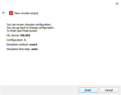
Figure 2. Summary
Open an existing schematic diagram
Save the schematic diagram
Save the schematic diagram as …
Note: Schematic Editor automatically backs up all opened and modified schematic diagrams periodically. The backup
file (with the .bak extension) is saved in the same location as the original file.
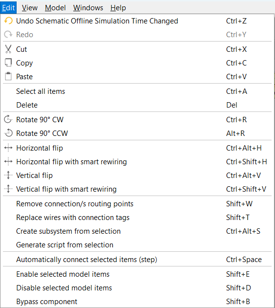
Undo an executed command
Redo an executed command
Cut the selected item(s)
Copy the selected item(s)
Paste items
Zoom In scene
Zoom Out scene
Zoom 1:1 (original zoom level)
Fit to view
Rotate 90’ CW selected component
Rotate 90’ CCW selected component
Flip the selected component horizontally
Flip the selected component vertically
Align selectionA menu of alignment commands detailed in Alignment commands
Model initialization script, initialize model namespace
Horizontal flip with smart rewiring – Flip selected items
horizontally while automatically adjusting the wiring connections.
Vertical flip – Flip selected items vertically.
Vertical flip with smart rewiring – Flip selected items
vertically while automatically adjusting the wiring connections.
Align selection – A menu of alignment commands detailed in Alignment commands.
Remove connection/s routing points – Remove all explicitly
created wire routing points for all wires in the schematic diagram. To remove wire
routing points for a single wire, right-click on that wire and then remove wire/s
routing points from the context menu.
Replace wires with connection tags – Removes selected
wires and replaces them with connection tags.
Create subsystem from selection – Create a subsystem from the currently selected
schematic elements.
Generate script from selection – Allows users to create an
API script based on selected components within Schematic. The software generates a
script that replicates the configuration and connections of those components.
Automatically connect selected items (step) – Allows
users to select items in the Schematic and have them automatically connected.
Enable selected model items – Allows users to enable
select items in the Schematic.
Disable selected model items – Allows users to disable
select items in the Schematic.
Bypass component – Allows users to temporarily remove
series-connected components from Schematic without deleting them. When a component
is bypassed, it is effectively removed from the compilation, and a short-circuit
is created between its terminals.
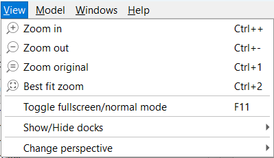
View menu
Zoom in - Zoom in action.
Zoom out - Zoom out action.
Zoom original - Allows users to reset the view of the
Schematic to its original scale and position.
Best fit zoom - Allows users to automatically adjust the
zoom level to fit the entire Schematic within the visible area of the window.
Toggle full screen/normal mode - Toggle between the full screen
and the normal view mode, which is available only when Schematic Editor is started
as standalone application.
Show/Hide docks – Enable or disable the selected dock.
Change perspective – Allows users to switch to different
perspectives(Real-time, TyphoonSim or Integrated). For more information about
perspectives, please refer to Simulation context definitions
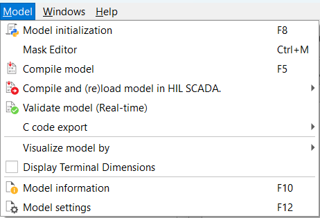
Model menu
Model initialization – Shows a dialog where model level variables can be defined.
These variables are visible throughout the model, so they can be used as values of
properties. For example, a Resistor resistance value can be set to R_init (where R_init is
defined at the model level using this dialog). In addition to variables, you can also add
any valid Python code.
Mask Editor – When selecting a component, opens the Mask Editor dialog box.
Compile model – Compile the current schematic model.
Compile and (re)load model in HIL SCADA – Compile the current
schematic model and load it into HIL SCADA.
C code export- Generate C code from a subset of a
model.
Visualize model by – Provides additional information on model
components based on the selected criteria.
Display Terminal Dimensions – Displays the number of dimensions
corresponding to signal processing component input/output terminals.
 Create a new schematic diagram using the New schematic diagram wizard (Figure 1, Figure 2). The wizard allows you to easily create a
new schematic diagram with hardware properties that match the HIL device in use. Hardware
properties can be set either manually or can be directly obtained from the connected HIL
device (by clicking on the Detect hardware settings button, Figure 1).
Create a new schematic diagram using the New schematic diagram wizard (Figure 1, Figure 2). The wizard allows you to easily create a
new schematic diagram with hardware properties that match the HIL device in use. Hardware
properties can be set either manually or can be directly obtained from the connected HIL
device (by clicking on the Detect hardware settings button, Figure 1).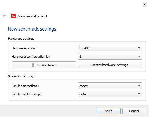
 Open an existing schematic diagram
 Save the schematic diagram
 Save the schematic diagram as …
Note: Schematic Editor automatically backs up all opened and modified schematic diagrams periodically. The backup file (with the .bak extension) is saved in the same location as the original file.
Save the schematic diagram as …
Note: Schematic Editor automatically backs up all opened and modified schematic diagrams periodically. The backup file (with the .bak extension) is saved in the same location as the original file. Undo an executed command
 Redo an executed command
 Cut the selected item(s)
 Copy the selected item(s)
 Paste items
 Zoom In scene
 Zoom Out scene
  Zoom 1:1 (original zoom level)
 Fit to view
 Rotate 90’ CW selected component
 Rotate 90’ CCW selected component
 Flip the selected component horizontally
 Flip the selected component vertically
 Align selectionA menu of alignment commands detailed in Alignment commands
 Model initialization script, initialize model namespace
 Model settings, opens model settings
 Compile the schematic diagram
 Compile and load the model into HIL SCADA
  Start TyphoonSim
 Stop TyphoonSim
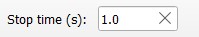 TyphoonSim simulation time
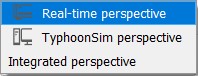 Change perspective