Variable Load (Generic)
Description of the Variable Load (Generic) component in Schematic Editor.
Component Overview
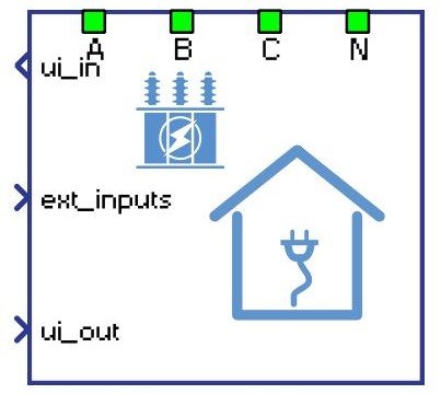
The Variable Load (Generic) component is a Schematic Editor library block from the Loads section, of the Grid Resources library.
Variable Load (Generic) block diagram
The component consists of two main parts: a high level control subsystem and a low level control subsystem with a power stage and necessary measurements included.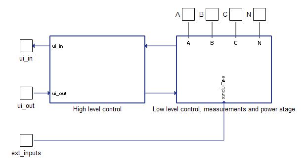
- PQ Control block - Contains regulators for active and reactive power control. The PQ Control block receives power references and measured powers after the transformer (grid side) and calculates reference output currents. These current references are fed to the low level control logic. This control block is active in the grid following mode of operation.
- Ramping elements Limit the ROC (rate of change) of the active power reference, reactive power reference, voltage reference, and frequency reference. The rate of change for each function is configured through a corresponding input signal.
- Current control block - Contains regulators for inner current control loops. Input signals to the Currents Control block are reference currents and measured currents before the transformer (load side).
- Fault state machine - Checks all measurements, signals the fault state, and sends an alarm message. It also immediately opens the MCB (main circuit breaker) on any detected fault. A list of implemented faults is shown in Table 4.
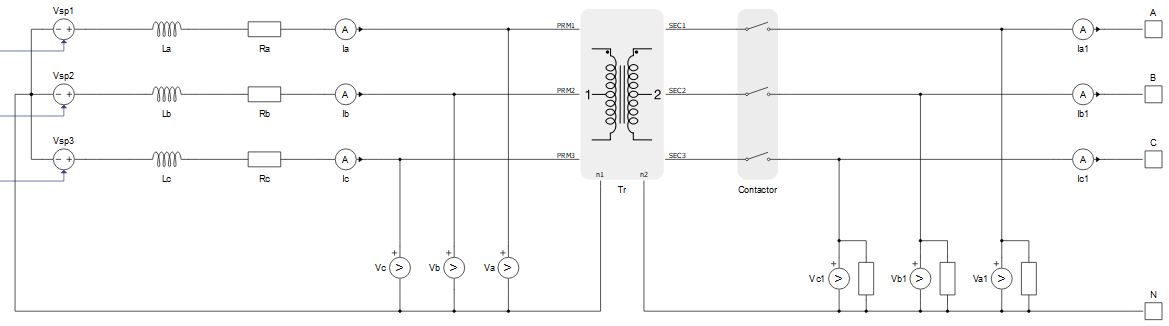
Variable Load (Generic) power stage
The power stage is shown in Figure 3. The main elements include the average model of the inverter, the input L filter, the transformer, and the MCB that connects the plant to the grid. The transformer can be excluded from the power stage if it is not necessary. Power stage elements are parametrized from the component dialog box.
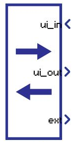
Variable Load (Generic) inputs and outputs
This component has one user interface input, one user interface output, and one external input. The user interface input and user interface output are each arrays of 40 elements, while the external input is an array of 5 elements. Table 1 describes the input signals and their order, while Table 2 describes the output signals and their order. Lastly, External inputs are reserved inputs that are not currently used.
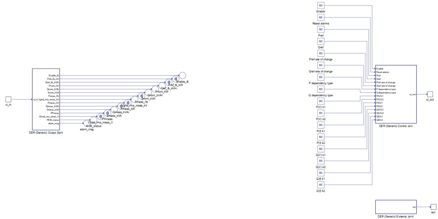
All these signals are also defined in the corresponding Variable Load (Generic) UI subsystem with built-in Probe components (for output signals) and SCADA Input components (for input signals), as shown in Table 3. These signals were split and joined by a properly configured DER (Generic) Output Split and DER (Generic) Control Join components. The Variable Load (Generic) UI is located in the same place in the Schematic Editor library as the Variable Load (Generic) component, and it can be unlinked from the library and adopted to the specific needs. Unit [pu] is associated to nominal values, which are either inserted as general tab parameters or derived from them.
| Number | Input | Description | Signal range | Default value |
|---|---|---|---|---|
| 0 | Enable | A digital input that enables the converter. The converter is enabled when the input value is high. | 0 or 1 | 0 |
| 1 | Reset alarms | A digital input that resets alarms if the converter is in a fault | 0 or 1 | 0 |
| 2 | Pref | An analog input that sets the active power consumption reference. [pu] | 0 | |
| 3 | Qref | An analog input that sets the reactive power consumption reference. [pu] | 0 | |
| 4 | Pref rate of change | An analog input that sets the rate of change of the active power reference ramping. [pu/s] | >= 0.001 | 0.1 |
| 5 | Qref rate of change | An analog input that sets the rate of change of the reactive power reference ramping. [pu/s] | >= 0.001 | 0.1 |
| 6 | P dependency type | An analog input that sets the type of dependence of active power consumption on voltage and frequency variation: None, quadratic or Taylor series | 0 or 1 or 2 | 0 |
| 7 | Q dependency type | An analog input that sets the type of dependence of active power consumption on voltage and frequency variation: None, Quadratic or Taylor series | 0 or 1 or 2 | 0 |
| 8 | P(V) k1 | An analog input that sets the coefficient k1 of the Taylor series for P(V) dependency | -100 to 100 | 0 |
| 9 | P(V) k2 | An analog input that sets the coefficient k2 of the Taylor series for P(V) dependency [1/pu] | -100 to 100 | 0 |
| 10 | P(f) k1 | An analog input that sets the coefficient k1 of the Taylor series for P(f) dependency | -100 to 100 | 0 |
| 11 | P(f) k2 | An analog input that sets the coefficient k2 of the Taylor series for P(f) dependency [1/pu] | -100 to 100 | 0 |
| 12 | Q(V) k1 | An analog input that sets the coefficient k1 of the Taylor series for Q(V) dependency | -100 to 100 | 0 |
| 13 | Q(V) k2 | An analog input that sets the coefficient k2 of the Taylor series for Q(V) dependency [1/pu] | -100 to 100 | 0 |
| 14 | Q(f) k1 | An analog input that sets the coefficient k1 of the Taylor series for Q(f) dependency | -100 to 100 | 0 |
| 15 | Q(f) k2 | An analog input that sets the coefficient k2 of the Taylor series for Q(f) dependency [1/pu] | -100 to 100 | 0 |
| 16 | V alarm upper limit* | Upper limit for the Grid voltage out of range error [pu] | > 1 | 1.5 |
| 17 | V alarm lower limit* | Lower limit for the Grid voltage out of range error [pu] | [0, 1) | 0.5 |
| 18 | F alarm upper limit* | Upper limit for the Grid frequency out of range error [pu] | > 1 | 1.5 |
| 19 | F alarm lower limit* | Lower limit for the Grid frequency out of range error [pu] | [0, 1) | 0.5 |
| 20 | S alarm upper limit* | Upper limit for the Over power protection [pu] | > 1 | 1.5 |
| 21 | I alarm upper limit* | Upper limit for the Over current protection [pu] | > 1 | 1.5 |
| 22-39 | reserved_ins | Inputs that are not used. | 0 |
* If the values for inputs 16 to 21 are all zeroes, default values will be used.
| Number | Output | Description |
|---|---|---|
| 0 | Enable_fb | A digital output describing the converter enable/disable state. The converter is enabled if the output is high. |
| 1 | Pref_fb_kW | An analog output with the instantaneous value of the applied power reference in the load. [kW] |
| 2 | Qref_fb_kVAr | An analog output with the instantaneous value of the applied reactive power reference in the load. [kVAr] |
| 3 | Pnom_kW | An analog output with the value of nominal active power of the load. [kW] |
| 4 | Qnom_kVAr | An analog output with the value of nominal reactive power of the load. [kVAr] |
| 5 | Snom_kVA | An analog output with the value of nominal apparent power of the load. [kVA] |
| 6 | Fmeas_Hz | An analog output reporting the value of the grid voltage frequency. [Hz] |
| 7 | Vgrid_rms_meas_kV | An analog output reporting the RMS value of the grid voltage, measured at the grid side of the transformer. [kV] |
| 8 | Pmeas_kW | An analog output reporting the instantaneous value of the three-phase active power output of the load. [kW] |
| 9 | Qmeas_kVAr | An analog output reporting the instantaneous value of the three-phase reactive power output of the load. [kVAr] |
| 10 | Smeas_kVA | An analog output reporting the instantaneous value of the three-phase apparent power output of the load. [kVA] |
| 11 | PFmeas | An analog output reporting the value of the converter output power factor. |
| 12 | Vload_rms_meas_V | An analog output reporting the RMS value of load voltage, measured at the load side of the transformer. [V] |
| 13 | MCB_status | A digital output reporting the information about the state of the main circuit breaker (contactor). The contactor is closed if the value is high. |
| 14 | alarm_msg | An analog output reporting the value of the alarm message. In order for the converter to return to normal operation after the alarm has been triggered, all alarms must be reset. |
| 15-39 | reserved_outs | Outputs that are not used. |
| Variable Load (Generic) UI | Variable Load (Generic) UI internals |
|---|---|
 |
 |
Variable Load (Generic) fault messages
| Code | Description |
|---|---|
| 0 | None of the alarms have been triggered |
| 1 | Over current protection. Input phase currents are greater than the maximum specified value. |
| 2 | Grid voltage out of range. Grid voltage is outside the specified range. This protection is active in grid following mode. If the voltage restores, the fault will be automatically reset. |
| 3 | Grid frequency out of range. Grid frequency is outside the specified range. This protection is active in grid following mode. If the frequency restores, the fault will be automatically reset. |
| 4 | Over power protection. Measured apparent power is greater than the maximum allowed apparent power. |
Power dependencies
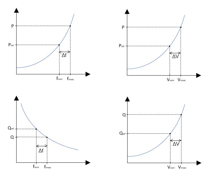
If power consumption is chosen to be dependent on grid voltage and/or frequency, there are two types of these dependencies: Quadratic dependency and Taylor series dependency.
Quadratic dependency
Load power consumption will not be constant and will quadratically depend on voltage and/or frequency variation, as shown in Figure 4.
Taylor series dependency
Load power consumption will not be constant and will depend on voltage and/or frequency variation according to the formulas:
,
where and
Component dialogue box and parameters
The Variable Load (Generic) component dialogue box consists of four tabs for specifying parameters of the component. Unit [pu] is associated to nominal values, which are inserted as general tab parameters or derived from them.
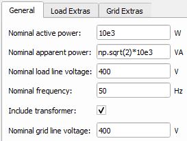
Tab: "1 - General"
In this component tab, general parameters of the Variable Load and the grid can be specified.
| Parameter | Code name | Description |
|---|---|---|
| Nominal active power | Pnom | Load nominal active power. [W] |
| Nominal apparent power | Snom | Load nominal apparent power. [VA] |
| Nominal converter line voltage | Vnom_LL | Load nominal line voltage (load side of the transformer). [V] |
| Nominal frequency | fnom | Load nominal frequency. [Hz] |
| Include transformer | include_transformer | Include the transformer in the Variable Load (Generic) power stage model. |
| Nominal grid line voltage | Vnom_sec_LL | Nominal line voltage of the grid (grid side of the transformer). [V] |
Tab: "2 - Load Extras"
In this component tab, additional parameters that are related to the Load can be specified.

| Parameter | Code name | Description |
|---|---|---|
| Transformer impedance | Zt_n | Determines the transformer impedance. The position of this transformer is shown in Figure 3. [pu] |
| Overload capability | opc_pu | Determines the overpower capability of the load. [pu] |
| Shunt resistance | Rshunt_pu | The value of the shunt resistances that are used for the measurement of phase voltages at the load input. The position of shunts is shown inFigure 3. [pu] |
| Faster execution rate | Tfast | The Faster execution rate, at which part of the inner signal processing of the component will be executed. Should be approximately 5 to 10 times faster than the Slower execution rate. [s] |
| Slower execution rate | Tslow | The Slower execution rate, at which part of the inner signal processing of the component will be executed. This execution rate is inherited by the connected UI subsystem. Should be approximately 5 to 10 times slower than the Faster execution rate. [s] |
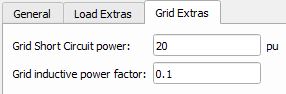
Tab: "3 - Grid Extras"
In this component tab, additional parameters that are related to the grid can be specified.
| Parameter | Code name | Description |
|---|---|---|
| Grid Short Circuit power | Sg_sc_pu | Short circuit apparent power of the grid that the converter is connected to. This parameter doesn't influence the power stage of the model, only the control part. Stable operation of the converter can be achived by tuning this parameter. [pu] |
| Grid inductive power factor | PFg | Power factor of the grid that the converter is connected to. This power factor occurs when the grid is short-circuited. This parameter doesn't influence the power stage of the model, only the control part. Stable operation of the converter can be achieved by adjusting this parameter. [pu] |
Example
Overall behavior and control methodologies can be better understood with the use of the given example:
Model name: variable load gen.tse
SCADA interface: variable load gen.cus
Path: /examples/models/microgrid/variable load/variable load (generic)