Constant Impedance Load
Description of the Constant Impedance Load component, for representing a three-phase balanced or unbalanced constant impedance load.
Component Overview
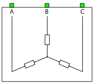
The Constant Impedance Load component, located in the Sinks library, represents a three-phase balanced or unbalanced constant impedance load. The possible combinations for the impedance are R, RL series connection, and RC series connection.
Tab: "General"
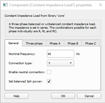
In this tab properties that are applicable to both balanced an unbalanced operation can be set.
| Parameter | Code name | Description |
|---|---|---|
| Nominal frequency | fn | Nominal grid frequency. |
| Connection type | conn_type | Combo box that defines the three-phase connection. Options are Y (wye or star) or Δ (delta or triangle) connections. |
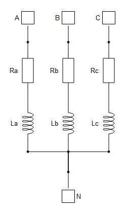
| Enable neutral connection | enable_neutral | By checking this box, an additional port that represents the neutral of a star connection will be added. |
| Set balanced 3ph power | set_balanced | By checking this field, the power will be balanced. If unchecked, the power can be defined per phase independently. |
Tab: "Three-phase"
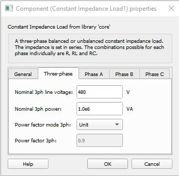
In this properties tab, power ratings of the load can be defined for balanced load option.
| Parameter | Code name | Description |
|---|---|---|
| Nominal 3ph line voltage | Vn_3ph | Nominal grid line to line voltage. |
| Nominal 3ph power | Sn_3ph | Desired three phase apparent power to be consumed. |
| Power factor mode 3ph | pf_mode_3ph | This field allows choosing among lag, lead, or unit power factors (inductive, capacitive or pure resistive load). |
| Power factor 3ph | pf_3ph | Power factor value applied on chosen power factor mode (when power factor mode is not set to unit). |
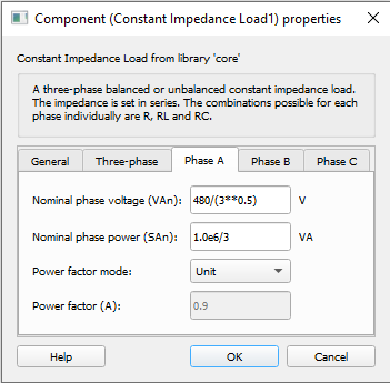
Tabs: "Phase A", "Phase B", "Phase C" for Y connection
These tabs are used when Set balanced 3ph power is not checked in the General tab. In these tabs you can enter the voltage, power, and power factor per phase. The parameters described here are for Y connection.
| Parameter | Code name | Description |
|---|---|---|
| Nominal phase voltage (VAn, VBn or VCn) | VAn, VBn or VCn | Nominal line to neutral voltage of the respective phase. |
| Nominal phase power (SAn, SBn or SCn) | SAn, SBn or SCn | Desired line to neutral apparent power consumed for the respective phase. |
| Power factor mode | pf_modeA, pf_modeB or pf_modeC | This field allows choosing among lag, lead or unit power factors (inductive, capacitive or pure resistive load) for the respective phase. |
| Power factor (A, B or C) | pfA, pfB or pfC | Power factor of the respective phase (when power factor mode is not set to unit). |
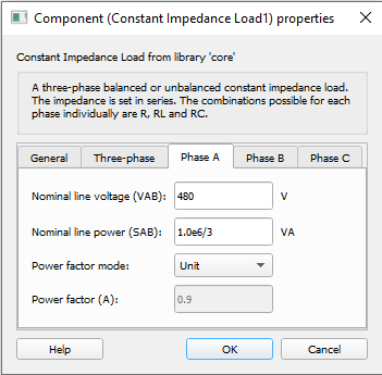
Tabs: "Phase A", "Phase B", "Phase C" for Δ connection
These tabs are used when Set balanced 3ph power is not checked in the General tab. In these tabs you can enter the voltage, power, and power factor per phase. The parameters described here are for Δ connection.
| Parameter | Code name | Description |
|---|---|---|
| Nominal line voltage (VAB, VBC or VCA) | VAB, VBC or VCA | Nominal line to line voltage between the respective phases. |
| Nominal line power (SAB, SBC or SCA) | SAB, SBC or SCA | Desired line to line apparent power consumed between the respective phases. |
| Power factor mode | pf_modeA, pf_modeB or pf_modeC | This field allows choosing among lag, lead or unit power factors (inductive, capacitive or pure resistive load) for the respective phase. |
| Power factor (A, B or C) | pfA, pfB or pfC | Power factor of the respective phase (when power factor mode is not set to unit). |
Example
Overall behavior can be better understood with the use of the given constant impedance load example:
Model name: meter_and_const_z_load.tse
SCADA interface: SCADA_Panel.cus
Path: /examples/models/microgrid/meter_and_constant_z_load/