Single-phase Variable Load
Description of the Single-phase Variable Load component in Schematic Editor.
Description
- Internal: Through SCADA inputs which are located inside of the component
- External: By using signal processing to calculate the references and provide those as signal processing inputs. Enabled by checking the corresponding property in the Tab: "Inputs/Outputs".
Control algorithm of a Single-phase Variable Load
- It's more robust: Its operation is mostly independent of the grid dynamics and it is less sensitive to grid events.
- It has no overshoot: Since it's based on a calculation, rather than a closed loop system, it does not exhibit overshoot and bandwidth issues.
- Steady-state error: Since there is no closed-loop feedback, it is not ensured that steady-state error in power measurements is equal to zero. However, calculations are designed in such a way that the steady-state error should remain reasonably small even under distorted voltage conditions.
- Electrical solver resources utilization: Since the component is comprised of several variable elements, it requires a significant amount of electrical solver resources.
- Necessity for snubber elements: In order to ensure the numerical stability of the circuit, snubber elements are added. Active power consumption of the snubber circuit represents the minimum active power that can be consumed by the load.
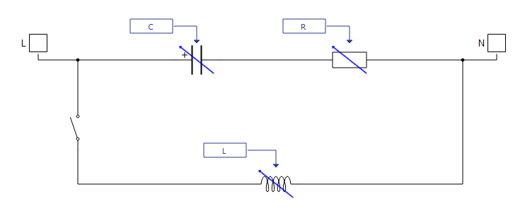
Single-phase Variable Load schematic block diagram
The component consists of an electrical part that consists of series RC connection in parallel with an inductance, as shown in Figure 2.
Component dialogue box and parameters
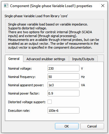
The Single-phase Variable Load component dialogue box consists of three tabs for specifying parameters of the component.
Tab: "General"
In this component tab, general parameters of the Single-phase Variable Load can be specified.
| Parameter | Name | Description |
|---|---|---|
| Nominal voltage | Vnom_rms | Load nominal voltage. [V] |
| Nominal frequency | fnom | Load nominal frequency. [Hz] |
| Nominal apparent power | Snom | Load nominal apparent power. [VA] |
| Nominal power factor | pf_nom | Load nominal power factor. |
| Distorted voltage support | include_harmonic | Enable distorted voltage support. |
| Harmonic order list | harmonic_list | List of harmonic order values that are expected to be present in the grid voltage. |
| Execution rate | execution_rate | Execution rate of the internal signal processing. [s] |
| CPU core | hil_cpu_core_id | Mapping CPU for signal processing components. |
Tab: "Advanced snubber options"
In this component tab, additional parameters that are related to the Load's snubber can be specified.
| Parameter | Name | Description |
|---|---|---|
| Snubber apparent power | Z_ind_pu | Apparent power that snubber consumes. [pu] |
| Power factor of snubber | pf_snubber | Power factor of the snubber. |
Tab: "Inputs/Outputs"
In this component tab, external inputs/outputs can be enabled.
| Parameter | Name | Description |
|---|---|---|
| Enable external references | enable_ext_ref | Enable external control mode. |
| Enable output vector | enable_outputs | Enable output vector with measurements. |
Single-phase Variable Load inputs and outputs
When the external control mode is enabled, the appropriate signal processing ports appear on the left side of the component. Available inputs are given in Table 4.
Available outputs are given in Table 5. These measurements are available through probes inside of the component, but can also be available as an output vector with 6 elements.
| Number | Input | Description | Signal range | Default value |
|---|---|---|---|---|
| 0 | Enable | A digital input that enables the load. The load is enabled when the input value is high. | 0 or 1 | 0 |
| 1 | Pref | An analog input that sets the active power consumption reference. [pu] | 0 to 1 | 0.5 |
| 2 | Qref | An analog input that sets the reactive power consumption reference. [pu] | 0 to 1 | 0.5 |
| 3 | ROC | An analog input that sets the rate of change of the power reference ramping. [pu/s] | >= 0.001 | 5 |
| Number | Output | Description |
|---|---|---|
| 0 | Enable_fb | A digital output describing the load's enable/disable state. The load is enabled if the output is high. |
| 1 | MCB_status | A digital output reporting the information about the state of the main circuit breaker (contactor). The contactor is closed if the value is high. |
| 2 | Pref_fb_kW | An analog output with the value of the applied active power reference in the load. [kW] |
| 3 | Qref_fb_kVAr | An analog output with the value of the applied reactive power reference in the load. [kVAr] |
| 4 | Pmeas_kW | An analog output reporting the value of the active power output of the load. [kW] |
| 5 | Qmeas_kVAr | An analog output reporting the value of the reactive power output of the load. [kVAr] |
| 6 | V | Voltage measurement. |
| 7 | I | Current measurement. |
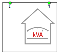
A dedicated Library Widget for controlling the Single-phase Variable Load component is available.