Variable passive components
Description of the variable passive components available in Schematic Editor
Variable Resistor, Variable Inductor, and Variable Capacitor are available in Schematic Editor Library Explorer. Resistance, inductance, and capacitance values are defined through a signal input to the corresponding component. Execution rate of the in signal processing part of the components is set to inherit.
Variable Resistor
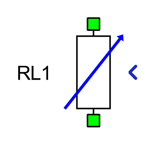
Variable Resistor is implemented as a controlled voltage source. In real-time/VHIL simulation, a snubber inductor connected in series is mandatory in order to ensure the stability of the component.
Ports
-
p_node (electrical)
- Variable Resistor p port
-
n_node (electrical)
- Variable Resistor n port
-
in
- Resistance value of the component [Ω]
Properties
- Inductance
 Inductance is not supported in TyphoonSim.
Enabling this property will not affect TyphoonSim simulation at all.
Inductance is not supported in TyphoonSim.
Enabling this property will not affect TyphoonSim simulation at all.- Value of the series snubber inductance [H]
- Initial current
- Initial current is not supported in
TyphoonSim. Enabling this property will not affect TyphoonSim simulation at all.
- Value of the inductor initial current [A]
Variable Inductor
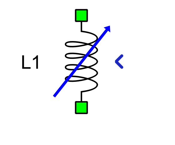
Variable Inductor is implemented as a current source with an optional resistance connected in parallel. Use of parallel resistor is strongly recommended to eliminate potential topological conflicts, bad cut sets, in the circuit. Value of the parallel resistance should be set with special care to avoid potential stability issues.
Ports
-
p_node (electrical)
- Variable Inductor p port
-
n_node (electrical)
- Variable Inductor n port
-
in
- Induction value of the component [H]
Properties
- Initial Flux
- Initial flux of the variable inductor [Wb]
- Use parallel resistance
- Enables or disables the snubber resistance
-
Resistance
- Available if Use parallel resistance is enabled
- Value of the snubber resistance [Ω]
Variable Capacitor
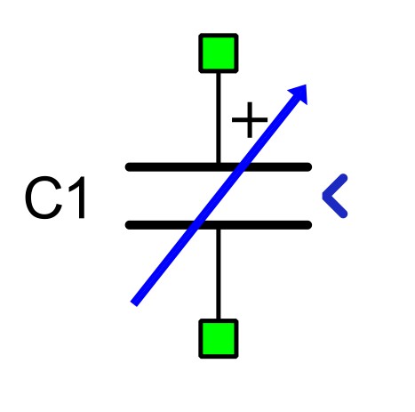
Variable Capacitor is implemented as a voltage source with an optional resistance connected in series. Use of a series resistor is strongly recommended to eliminate potential topological conflicts, bad voltage loops, in the circuit. The value of the series resistance should be set with special care to avoid potential stability issues.
Ports
-
p_node (electrical)
- Variable Inductor p port
-
n_node (electrical)
- Variable Inductor n port
-
in
- Induction value of the component [H]
Properties
- Initial charge
- Initial charge of the variable capacitor [C]
-
Use series resistance
- Enables or disables the series resistance
-
Resistance
- Available if Use series resistance is enabled
- Value of the series resistance [Ω]