Parallel RLC Branch
Description of the Parallel RLC Branch component in Schematic Editor
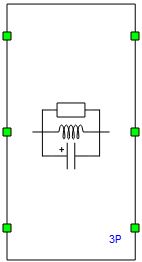
Parallel RLC Branch represents a parallel connection of a resistor, inductor, and capacitor. Parallel RLC Branch can be either single phase or three phase. The elements in the branch can be specified by changing the branch type.
Ports
-
P1_pos
- Available if Phases is set to Single-Phase or Three-Phase
- Phase 1 positive polarity port
-
P2_pos
- Available if Phases is set to Three-Phase
- Phase 2 positive polarity port
-
P3_pos
- Available if Phases is set to Three-Phase
- Phase 3 positive polarity port
-
P1_neg
- Available if Phases is set to Single-Phase or Three-Phase
- Phase 1 negative polarity port
-
P2_neg
- Available if Phases is set to Three-Phase
- Phase 2 negative polarity port
-
P3_neg
- Available if Phases is set to Three-Phase
- Phase 3 negative polarity port
Properties
-
Phases
- Number of phases for the parallel branch
- Three-Phase or Single-Phase branches are available
-
Branch Type
- Type of elements contained in the parallel branch
- RLC, R, L, C, RL, RC, or LC types are available
-
Resistance
- Available if Branch Type is set to RLC, R, RL, or RC
- Value of resistance in the parallel branch [Ω]
-
Inductance
- Available if Branch Type is set to RLC, L, RL, or LC
- Value of inductance in the parallel branch [H]
-
Capacitance
- Available if Branch Type is set to RLC, C, RC, or LC
- Value of capacitance in the parallel branch [F]
-
Initial current
- Available if Phases is set to Single-Phase and Branch Type is RLC, L, RL, or LC
- Initial inductor current [A]
-
Initial voltage
- Available if Phases is set to Single-Phase and Branch Type is RLC, C, RC, or LC
- Initial capacitor voltage [V]