VBR Variable Load
Description of the legacy voltage behind reactance variable load component from the Sinks library.
VBR Variable Load Overview
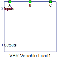
The variable voltage behind reactance load component, located in the Sinks library, represents a three-phase balanced variable load.
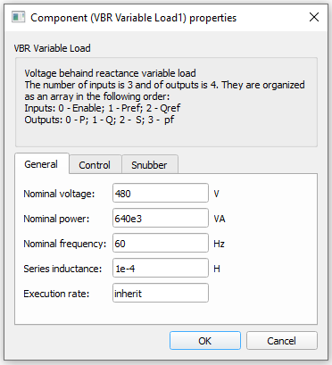
Tab: "General"
| Parameter | Code name | Description |
|---|---|---|
| Nominal voltage | Vn | Nominal voltage |
| Nominal power | Sn | Nominal power |
| Nominal frequency | fn | Nominal grid frequency. |
| Series inductance | L | Series inductance of the component, resistance is calculated using nominal power. |
| Execution rate | execution_rate | Execution rate in seconds. |
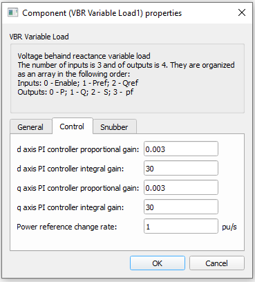
Tab: "Control"
In this properties tab, it is defined gains for PI regulator for d and q axes.
| Parameter | Code name | Description |
|---|---|---|
| d axis PI controller proportional gain | Id_Kp | Proportional gain for PI regulator in d axe. |
| d axis PI controller integral gain | Id_Ki | Integral gain for PI regulator in d axe. |
| q axis PI controller proportional gain | Iq_Kp | Proportional gain for PI regulator in q axe |
| q axis PI controller integral gain | Iq_Ki | Integral gain for PI regulator in q axe. |
| Automatically PI gains | PIgains | Combo box for calculation PI gains. |
| Display gains | display | Display button shows PI gains in message console |
Tabs: "Snubber"
Snubber consists of three resistance in star topology, connected as shunt in system.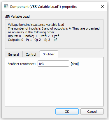
| Parameter | Code name | Description |
|---|---|---|
| Snubber resistance | Rsnub | Snubber resistance |
Example
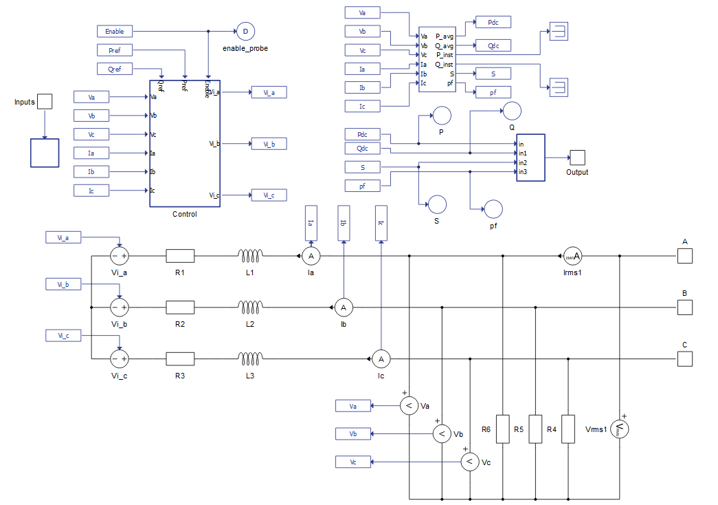
Overall behavior can be better understood with the use of the given variable VBR load example:
Model name: variable_load.tse
SCADA interface: SCADA_Panel.cus
Path: /examples/models/microgrid/variable_load/