DER (Generic) Output Split
Description of the DER (Generic) Output Split component for splitting the signal processing outputs of a DER (Generic) component.
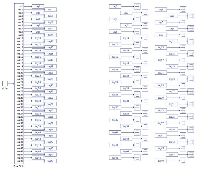
The DER (Generic) Output Split is a component located in the Infrastructure library section of the Grid Resources. The DER (Generic) Output Split is a masked bus split that is compatible with the signal processing outputs of the DER (Generic) components: Battery ESS (Generic), PV Power Plant (Generic), Wind Power Plant (Generic), Diesel Genset (Generic), Bidirectional AC-DC Converter (Generic), and DC-DC Converter (Generic). Its inputs are vectors of fixed size, while its outputs are scalar values. Its size and number of output ports are changed dynamically based on the selected component and chosen measurements.
Tab: "1 - DER"
In this Properties tab, the DER generic component that the Split is intended to be used with is selected. Depending on the chosen component, measurements related to corresponding component will be visible for selection.
| Parameter | Code name | Description |
|---|---|---|
| Component | component_select | Through this combobox the DER component is selected. |
Tab: "2 - Converter status"
In this Properties tab, feedbacks for basic converter status can be enabled.
| Parameter | Code name | Description |
|---|---|---|
| Converter enabled | Enable_fb | Checkbox that enables measurement of enable feedback measurement |
| Converter mode | Converter_mode_fb | Checkbox that enables measurement of feedback information of converter operating mode |
| MCB status | MCB_status | Checkbox that enables measurement of feedback for main circuit breaker |
| Operating state code | state | Checkbox that enables measurement of converter's state machine operating state |
| Alarm message | alarm_msg | Checkbox that enables measurement of current alarm message |
| LVRT active status | Lvrt_active_status | Checkbox that enables measurement of LVRT active status |
Tab: "3 - Nominal values"
In this Properties tab, measurement of nominal values of the converter can be enabled.
| Parameter | Code name | Description |
|---|---|---|
| Nominal active power | Pnom_kW | Checkbox that enables measurement of nominal active power of the converter |
| Nominal reactive power | Qnom_kVAr | Checkbox that enables measurement of nominal reactive power of the converter |
| Nominal apparent power | Snom_kVA | Checkbox that enables measurement of nominal apparent power of the converter |
| Nominal line voltage | Vnom_LL_V | Checkbox that enables measurement of nominal grid line voltage of the converter |
| Nominal frequency | Fnom_Hz | Checkbox that enables measurement of nominal frequency of the converter |
| Nominal battery capacity | Batt_cap_nom_Ah | Checkbox that enables measurement of nominal battery capacity |
| Nominal wind speed | nom_wind_speed_m_per_s | Checkbox that enables measurement of nominal wind speed |
Tab: "4 - Reference feedbacks"
In this Properties tab, feedbacks of references for various signals can be enabled.
| Parameter | Code name | Description |
|---|---|---|
| Active power reference | Pref_fb_kW | Checkbox that enables measurement of active power reference |
| Rective power reference | Qref_fb_kVAr | Checkbox that enables measurement of reactive power reference |
| Line voltage reference | Vrms_ref_fb_V | Checkbox that enables measurement of line voltage reference |
| Grid frequency reference | Fref_fb_Hz | Checkbox that enables measurement of frequency reference |
Tab: "5 - Power"
In this Properties tab, power measurement can be enabled.
| Parameter | Code name | Description |
|---|---|---|
| Active power | Pmeas_kW | Checkbox that enables total active power measurement output |
| Phase A active power | Pa_meas_kW | Checkbox that enables phase A active power measurement output |
| Phase B active power | Pb_meas_kW | Checkbox that enables phase B active power measurement output |
| Phase C active power | Pc_meas_kW | Checkbox that enables phase C active power measurement output |
| Reactive power | Qmeas_kVAr | Checkbox that enables total reactive power measurement output |
| Phase A reactive power | Qa_meas_kVAr | Checkbox that enables phase A reactive power measurement output |
| Phase B reactive power | Qb_meas_kVAr | Checkbox that enables phase B reactive power measurement output |
| Phase C reactive power | Qc_meas_kVAr | Checkbox that enables phase C reactive power measurement output |
| Apparent power | Smeas_kVA | Checkbox that enables total apparent power measurement output |
| Power factor | PFmeas | Checkbox that enables power factor measurement output |
Tab: "6 - Voltage"
In this Properties tab, voltage measurements can be enabled.
| Parameter | Code name | Description |
|---|---|---|
| Grid line voltage | Vgrid_rms_meas_kV | Checkbox that enables grid line voltage measurement output |
| Converter line voltage | Vconv_rms_meas_V | Checkbox that enables converter line voltage measurement output |
Tab: "7 - Frequency"
In this Properties tab, frequency measurement can be enabled.
| Parameter | Code name | Description |
|---|---|---|
| Frequency | Fmeas_Hz | Checkbox that enables frequency measurement output |
Tab: "8 - DER specific"
In this Properties tab, DER specific measurement can be enabled. These measurements are specific for a particular DER component, such as Battery current (specific for Battery ESS (Generic)) or Wind speed (specific for Wind Power Plant (Generic)).
| Parameter | Code name | Description |
|---|---|---|
| Battery current | Ibatt_A | Checkbox that enables battery current measurement output |
| Battery voltage | Vbatt_V | Checkbox that enables battery voltage measurement output |
| SOC | SOC | Checkbox that enables battery state of charge measurement output |
| SOH | SOH | Checkbox that enables battery state of health measurement output |
| Available power | Available_Ppv_kW | Checkbox that enables available PV power measurement output |
| Power curtailment status | curtailment_status | Checkbox that enables power curtailment status measurement output |
| Rotational speed | rotational_speed_RPM | Checkbox that enables wind turbine rotational speed measurement output |
| Wind speed | wind_speed_m_per_s | Checkbox that enables wind speed measurement output |
| Turbine stalled | turbine_stalled | Checkbox that enables turbine stalled feedback measurement output |
| Pitch control on | pitch_ctrl_on | Checkbox that enables pitch control feedback measurement output |
| Average wind speed during first time interval | avg_wind_speed_1 | Checkbox that enables average wind speed during first time interval measurement output |
| Average wind speed during second time interval | avg_wind_speed_2 | Checkbox that enables average wind speed during second time interval measurement output |
| Average wind speed during storm control related time interval | avg_wind_speed_sc | Checkbox that enables average wind speed during storm control related time interval measurement output |
| Default turbine protection tripped | prot_trip | Checkbox that enables default wind turbine protection trip feedback measurement output |
| Power reduction on | P_red_on | Checkbox that enables power reduction on feedback measurement output |
| Power cut out | P_cut_out | Checkbox that enables power cut out feedback measurement output |
| Generator line voltage | Vgen_rms_meas_V | Checkbox that enables generator line voltage measurement output |
| Generator speed | Gen_speed_RPM | Checkbox that enables generator speed measurement output |
| DC voltage | Vdc_V | Checkbox that enables DC voltage measurement output |
| DC current | Idc_A | Checkbox that enables DC current measurement output |
| DC voltage in | Vdc_in | Checkbox that enables DC voltage in measurement output |
| DC voltage out | Vdc_out | Checkbox that enables DC voltage out measurement output |
| DC current in | Idc_in | Checkbox that enables DC current in measurement output |
| DC current out | Idc_out | Checkbox that enables DC current out measurement output |
| Active power in | P_in | Checkbox that enables active power in measurement output |
| Active power out | P_out | Checkbox that enables active power out measurement output |
Example
Overall behavior can be better understood with the use of example models for DER Generic components:
Model names: battery ess gen.tse, pv plant gen.tse, wind power plant gen.tse, bidirectional AC-DC converter gen.tse
SCADA interfaces: battery ess gen.cus, pv plant gen.cus, wind power plant gen.cus, bidirectional AC-DC converter gen.cus
Paths:\examples\models\microgrid\energy storage\battery ess (generic), \examples\models\microgrid\pv plant\pv plant (generic), \examples\models\microgrid\wind turbine\wind power plant (generic), \examples\models\microgrid\bidirectional AC-DC converter\bidirectional AC-DC converter (generic)