DER (Generic) Control Join
Description of the DER (Generic) Control Join component, for enabling easy selection of control signals of interest in order to enable model control of a Generic DER component inverter.
The DER (Generic) Control Join is a component located in the Infrastructure library section of the Grid Resources library. The DER (Generic) Control Join is a masked bus join that is compatible with the signal processing control inputs of the DER (Generic) components: Battery ESS (Generic), PV Power Plant (Generic), Wind Power Plant (Generic), Diesel Genset (Generic), Bidirectional AC-DC Converter (Generic), and DC-DC Converter (Generic). Its purpose is to enable easy selection of control signals of interest in order to enable model control of the converter. Signals that are not selected to be fed externally are sent in the form of constant, default values.
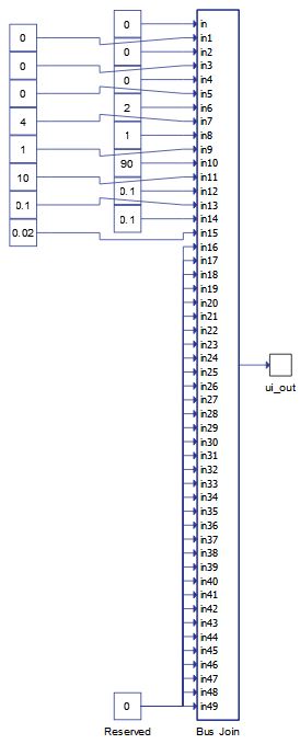
Component inputs are scalar values, while its output is a fixed size vector. Its size and number of output ports are changed dynamically based on chosen measurements. For a more detailed information on meaning of each control signal, please refer to documentation of a corresponding DER (Generic) component.
Tab: "1 - DER"
In this Properties tab, the DER generic component that the Join is intended to be used with is selected. Depending on the chosen component, control signals related to corresponding component will be visible for selection.
| Parameter | Code name | Description |
|---|---|---|
| Component | component_select | Through this combobox the DER component is selected. |
Tab: "2 - Converter status"
In this Properties tab, basic controls regarding converter status can be selected.
| Parameter | Code name | Description |
|---|---|---|
| Enable | Enable | Checkbox that enables an enable signal to be fed externally |
| Converter mode | Converter_mode | Checkbox that enables a converter mode signal to be fed externally |
| Reset alarms | Reset_alarms | Checkbox that enables a reset alarms signal to be fed externally |
| Operation mode | Operation_mode | Checkbox that enables an operation mode signal to be fed externally |
Tab: "3 - References and droops"
In this Properties tab, control inputs related to reference values and droop control parameters can be selected.
| Parameter | Code name | Description |
|---|---|---|
| Active power reference | Pref | Checkbox that enables an active power reference signal to be fed externally |
| Reactive power reference | Qref | Checkbox that enables a reactive power reference signal to be fed externally |
| Frequency droop offset | Frequency_droop_offset | Checkbox that enables a frequency droop offset signal to be fed externally |
| Frequency droop coeff | Frequency_droop_coeff | Checkbox that enables a frequency droop coeff signal to be fed externally |
| Voltage droop offset | Voltage_droop_offset | Checkbox that enables a voltage droop offset signal to be fed externally |
| Voltage droop coeff | Voltage_droop_coeff | Checkbox that enables a voltage droop coeff signal to be fed externally |
| Voltage rms reference | Vrms_ref | Checkbox that enables a voltage rms reference signal to be fed externally |
| Frequency reference | Fref | Checkbox that enables a frequency reference signal to be fed externally |
| Active power reference rate of change | Pref_rate_of_change | Checkbox that enables an active power reference rate of change signal to be fed externally |
| Reactive power reference rate of change | Qref_rate_of_change | Checkbox that enables a reactive power reference rate of change signal to be fed externally |
| Voltage rms reference rate of change | Vrms_ref_rate_of_change | Checkbox that enables a voltage rms reference rate of change signal to be fed externally |
| Frequency reference rate of change | Fref_rate_of_change | Checkbox that enables a frequency reference rate of change signal to be fed externally |
| Active power curtailment | Pcurtailment | Checkbox that enables an active power curtailment signal to be fed externally |
| Active power curtailment rate of change | Pcurtailment_rate_of_change | Checkbox that enables an active power curtailment rate of change signal to be fed externally |
| MPPT rate of change | MPPT_rate_of_change | Checkbox that enables an MPPT rate of change signal to be fed externally |
| Power droop coeff | Power_droop_coeff | Checkbox that enables a power droop coeff signal to be fed externally |
Tab: "4 - DER specific"
In this Properties tab, control inputs related to specific properties of a DER can be selected.
| Parameter | Code name | Description |
|---|---|---|
| Max SOC | Max_SOC | Checkbox that enables a maximum SOC signal to be fed externally |
| Min SOC | Min_SOC | Checkbox that enables a minimum SOC signal to be fed externally |
| Enable storm control | Enable_storm_control | Checkbox that enables an enable storm control signal to be fed externally |
| Int1 wind speed max | int1_wind_speed_max | Checkbox that enables an int1 wind speed max signal to be fed externally |
| Int2 wind speed max | int2_wind_speed_max | Checkbox that enables an int2 wind speed max signal to be fed externally |
| Active power reduction wind speed (SC) | P_reduction_wind_speed__SC_ | Checkbox that enables an active power reduction wind speed (SC) signal to be fed externally |
| Average wind speed max (SC) | Average_wind_speed_max__SC_ | Checkbox that enables an average wind speed max (SC) signal to be fed externally |
| Cut out wind speed (SC) | Cut_out_wind_speed__SC_ | Checkbox that enables a cut out wind speed (SC) signal to be fed externally |
| Time interval 1 | time_interval_1 | Checkbox that enables a time interval 1 signal to be fed externally |
| Time interval 2 | time_interval_2 | Checkbox that enables a time interval 2 signal to be fed externally |
| Recovery time | Recovery_time | Checkbox that enables a recovery time signal to be fed externally |
| Time interval (SC) | time_interval__SC_ | Checkbox that enables a time interval (SC) signal to be fed externally |
| Active power dependency type | P_dependency_type | Checkbox that enables an active power dependency type signal to be fed externally |
| Reactive power dependency type | Q_dependency_type | Checkbox that enables a reactive power dependency type signal to be fed externally |
| P(V) k1 | P_V_k1 | Checkbox that enables a P(V) k1 signal to be fed externally |
| P(V) k2 | P_V_k2 | Checkbox that enables a P(V) k2 signal to be fed externally |
| P(f) k1 | P_f_k1 | Checkbox that enables a P(f) k1 signal to be fed externally |
| P(f) k2 | P_f_k2 | Checkbox that enables a P(f) k2 signal to be fed externally |
| Q(V) k1 | Q_V_k1 | Checkbox that enables a Q(V) k1 signal to be fed externally |
| Q(V) k2 | Q_V_k2 | Checkbox that enables a Q(V) k2 signal to be fed externally |
| Q(f) k1 | Q_f_k1 | Checkbox that enables a Q(f) k1 signal to be fed externally |
| Q(f) k2 | Q_f_k2 | Checkbox that enables a Q(f) k2 signal to be fed externally |
Tab: "5 - Grid codes"
In this Properties tab, control inputs related to Grid codes of a DER can be selected.
| Parameter | Code name | Description |
|---|---|---|
| LVRT enable | LVRT_enable | Checkbox that enables an LVRT enable signal to be fed externally |
| LVRT reactive power contribution | LVRT_Q_contribution | Checkbox that enables an LVRT reactive power contribution signal to be fed externally |
| LVRT active power set | LVRT_P_set | Checkbox that enables an LVRT active power set signal to be fed externally |
| VoltVAr enable | VoltVAr_enable | Checkbox that enables a VoltVAr enable signal to be fed externally |
| HzWatt enable | HzWatt_enable | Checkbox that enables a HzWatt enable signal to be fed externally |
| VoltWatt enable | VoltWatt_enable | Checkbox that enables a VoltWatt enable signal to be fed externally |
Tab: "6 - Protection"
In this Protection tab, control inputs related to protection of a DER can be selected.
| Parameter | Code name | Description |
|---|---|---|
| Voltage alarm upper limit | V_alarm_upper_limit | Checkbox that enables a voltage alarm upper limit signal to be fed externally |
| Voltage alarm lower limit | V_alarm_lower_limit | Checkbox that enables a voltage alarm lower limit signal to be fed externally |
| Frequency alarm upper limit | F_alarm_upper_limit | Checkbox that enables a frequency alarm upper limit signal to be fed externally |
| Frequency alarm lower limit | F_alarm_lower_limit | Checkbox that enables a frequency alarm lower limit signal to be fed externally |
| Apparent power alarm upper limit | S_alarm_upper_limit | Checkbox that enables an apparent power alarm upper limit signal to be fed externally |
| Current alarm upper limit | I_alarm_upper_limit | Checkbox that enables a current alarm upper limit signal to be fed externally |
| Current alarm timeout | I_alarm_timeout | Checkbox that enables a current alarm timeout signal to be fed externally |
| Drift alarm frequency bound | Drift_alarm_freq_bound | Checkbox that enables a drift alarm frequency bound signal to be fed externally |
| Sync timeout | Sync_timeout | Checkbox that enables a sync timeout signal to be fed externally |
Example
Overall behavior can be better understood with the use of example models for DER Generic components:
Model names: battery ess gen.tse, pv plant gen.tse, wind power plant gen.tse, bidirectional AC-DC converter gen.tse
SCADA interfaces: battery ess gen.cus, pv plant gen.cus, wind power plant gen.cus, bidirectional AC-DC converter gen.cus
Path: \examples\models\microgrid\energy storage\battery ess (generic), \examples\models\microgrid\pv plant\pv plant (generic), \examples\models\microgrid\wind turbine\wind power plant (generic), \examples\models\microgrid\bidirectional AC-DC converter\bidirectional AC-DC converter (generic)