Frequency droop in generic DER components
Description of the Frequency Droop unit calculation function inside of Generic DER components
Implementation
The difference between and must remain within the range [- , + ]. If the difference exceeds this range, it will be limited to either - or + , as appropriate.
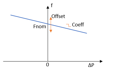
Changing the Droop Offset value shifts the nominal droop frequency up or down, while changing the Coefficient value affects the slope of the droop characteristics (a higher coefficient value leads to a higher slope). Active power error is calculated by subtracting filtered measurement of the active power from the reference active power. A simple first-order low-pass filter is used for this purpose. Active power error is limited by the generic DER's Maximal Active Power setting.
Parameters and I/O
- Parameters
- Active power measurement low pass filter cut-off frequency (defined with 0.1*generic DER nominal frequency)
- Execution rate (equal to slower execution rate of the generic DER component)
- Inputs
- Active power reference
- Active power measurement
- Frequency droop coefficient
- Frequency droop enable
- Droop nominal frequency (generic DER nom frequency + frequency droop offset)
- Output
- Frequency reference value