LVRT in generic DER components
Description of the Low Voltage Ride Through (LVRT) functionality available for generic DER components
Implementation
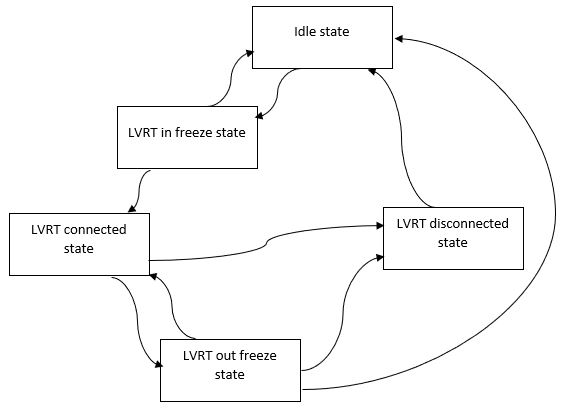
| State num | State name | Description |
|---|---|---|
| 1 | Idle | If PCC voltage drops below the voltage level defined by the last LVRT point, state 2 will become active. |
| 2 | LVRT in freeze | After seconds, PCC voltage is captured. If it is higher than the last voltage level, LVRT logic will return to state 1. Otherwise, it will go to state 3. |
| 3 | LVRT connected | During this state, the DER will remain connected and active, and reactive power contributions based on the captured voltage will be applied. The connection interval will be continuously updated based on the current DER voltage and the defined LVRT curve. If the internal timer becomes greater than the calculated connection interval, the LVRT logic will change to state 5. If the DER voltage becomes higher than the last LVRT voltage point, or lower than the first LVRT voltage point, the LVRT logic will change to state 4. |
| 4 | LVRT out freeze | After seconds, DER voltage is captured. If it is higher than the last LVRT voltage point, LVRT logic will change to state 1. If it is lower than the first LVRT voltage point, the LVRT logic will change to state 5 if possible, otherwise it will return to state 3. The same active and reactive power contributions will be applied, as in state 3. |
| 5 | LVRT disconnected | The LVRT will stay in this state until the DER PCC voltage is not fully restored (above the last LVRT voltage point). While in this state, the DER is disconnected from the grid and the fault state is active. |
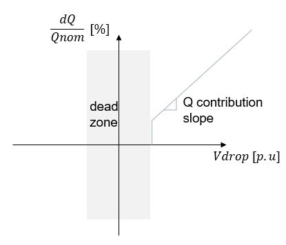
The LVRT functionality is only active in the Grid Following operation mode. Active and reactive power contributions are calculated based on the LVRT Q contribution and LVRT P set inputs. During LVRT states 3 and 4, current reactive power is increased by the reactive power contribution calculated from the LVRT Q contribution input and the measured voltage dip. The dead zone is defined by the last LVRT point voltage value. The active power reference will be overwritten by the LVRT P set input during states 3 and 4.
If other grid functionalities (VoltVAr, HzWatt, and VoltWatt) are enabled, then these curves have priority over the LVRT active and reactive power contribution settings.
Parameters and I/O
- Parameters
- LVRT curve points (voltage and time axis)
- Freeze time value (equal to 1/generic DER nominal frequency)
- Execution rate (equal to slower execution rate of the generic DER component)
- Inputs
- Input measured voltage
- LVRT enable
- Active power reference
- Reactive power reference
- LVRT Q contribution slope value
- LVRT P set value
- Output
- Disconnect signal
- LVRT active signal
- Modified active power reference signal
- Modified reactive power reference signal