PV Power Plant (Generic)
Description of the PV Power Plant (Generic) component in Schematic Editor.
Component Overview
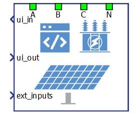
The PV Power Plant (Generic) component is a Schematic Editor block from the PV Power Plant library section, of the Grid Resources library. It is capable of operating in grid following mode, with active power curtailment supported.
PV Power Plant (Generic) functional block diagram and main control functionality
The component consists of two main parts: a high level control subsystem and a low level control subsystem with a power stage and necessary measurements included.
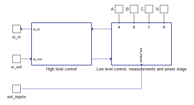
High level control subsystem main parts are:
- PQ Control block - Contains regulators for active and reactive power control. The PQ Control block receives power references and measured powers after the transformer (grid side) and calculates reference output currents. These current references are fed to the low level control logic.
- MPPT Control block - Optimizes PV Power Plant operation to extract maximum power output under varying environmental conditions, taking into consideration temperature and irradiance.
- Ramping elements - Limit the ROC (rate of change) of the active power reference, reactive power reference, voltage reference, and frequency reference. The rate of change for each function is configured through a corresponding input signal.
- Main state machine - Controls and checks overall functionality of the plant. Operational plant states are described in Table 5.
- Currents control block - Contains regulators for inner current control loops. Input signals to the Currents Control block are reference currents and measured currents before the transformer (converter side).
- Fault state machine - Checks all measurements, signals the fault state, and sends an alarm message. It also immediately opens the MCB (main circuit breaker) on any detected fault. A list of implemented faults is shown in Table 6.
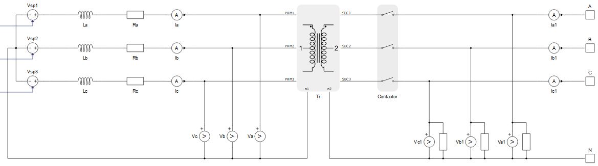
PV Power Plant (Generic) power stage
The power stage is shown in Figure 3. The main elements include the average model of the inverter, the input L filter, the transformer, and the MCB that connects the plant to the grid. The transformer can be excluded from the power stage if it is not necessary. Power stage elements are parametrized from the component dialog box.
PV Power Plant (Generic) component inputs and outputs
This component has one user interface input, one user interface output, and one external input. The user interface input and user interface output are each arrays of 40 elements, while the external input is an array of 5 elements.Table 1 describes the input signals and their order, while Table 2 describes the output signals and their order. Lastly, Table 3 describes the external PV Plant input signals and their order.
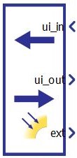
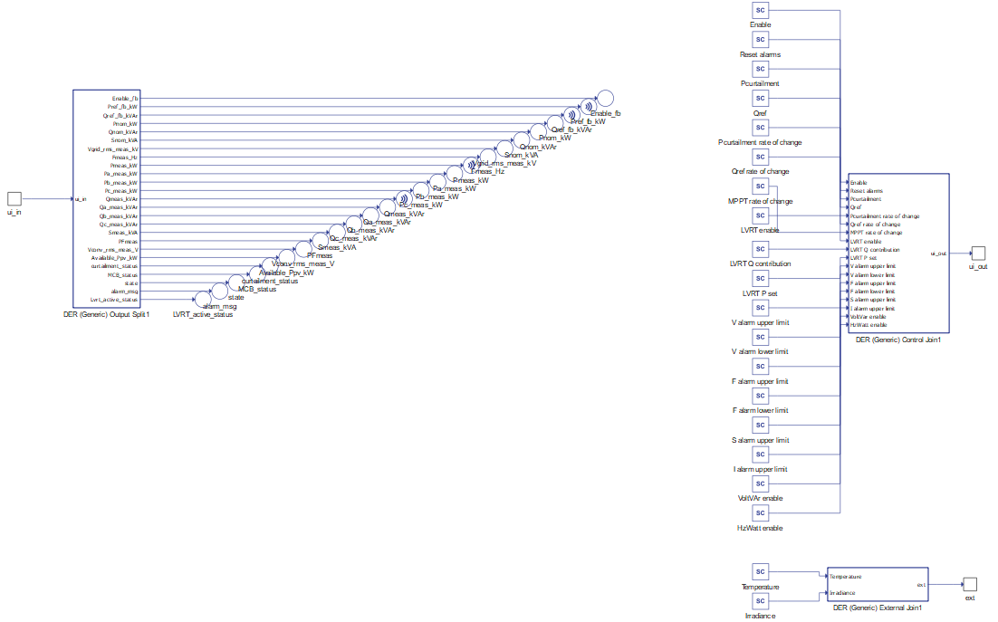
All these signals are also defined in the corresponding PV Power Plant (Generic) UI subsystem with built-in Probe components (for output signals) and SCADA Input components (for input signals), as shown in Table 4. These signals were split and joined by properly configured DER (Generic) Output Split and DER (Generic) Control Join components. The PV Power Plant (Generic) UI subsystem is located in the same place in the Schematic Editor library as the PV Power Plant (Generic) component, and it can be unlinked from the library and adopted to the specific needs. Unit [pu] is associated to nominal values, which are either inserted as general tab parameters or derived from them.
| Number | Input | Description | Signal range | Default value |
|---|---|---|---|---|
| 0 | Enable | A digital input that enables the converter. The converter is enabled when the input value is high. | 0 or 1 | 0 |
| 1 | Reset alarms | A digital input that resets alarms if the converter is in a fault | 0 or 1 | 0 |
| 2 | Pcurtailment | An analog input that limits the maximum output power. [pu] | >= 0 | 0 |
| 3 | Qref | An analog input that sets the reactive power reference. This reference is active in grid following and droop mode. [pu] | 0 | |
| 4 | Pcurtailment rate of change | An analog input that sets the rate of change of the active power curtailment reference ramping, when the active power curtailment reference value decreases. [pu/s] | >= 0.001 | 0.1 |
| 5 | Qref rate of change | An analog input that sets the rate of change of the reactive power reference ramping. [pu/s] | >= 0.001 | 0.1 |
| 6 | MPPT rate of change | An analog input that sets the rate of change of the active power when active power is controlled through MPPT algorithm. [pu/s] | >= 0.001 | 0.1 |
| 7 | LVRT enable | Digital input that enables the LVRT unit. The LVRT unit is enabled when the input value is high. | 0 or 1 | 0 |
| 8 | LVRT Q contribution | An analog input that specifies additional reactive power contribution per percent of voltage drop in the case of a LVRT event. [%] | >= 0 | 2 |
| 9 | LVRT P set | An analog input that defines the active power reference in the case of a LVRT event. [pu] | >= 0 | 1 |
| 10 | V alarm upper limit* | Upper limit for the Grid voltage out of range error [pu] | > 1 | 1.5 |
| 11 | V alarm lower limit* | Lower limit for the Grid voltage out of range error [pu] | [0, 1) | 0.5 |
| 12 | F alarm upper limit* | Upper limit for the Grid frequency out of range error [pu] | > 1 | 1.5 |
| 13 | F alarm lower limit* | Lower limit for the Grid frequency out of range error [pu] | [0, 1) | 0.5 |
| 14 | S alarm upper limit* | Upper limit for the Over power protection [pu] | > 1 | 1.5 |
| 15 | I alarm upper limit* | Upper limit for the Over current protection [pu] | > 1 | 1.5 |
| 16 | VoltVAr enable | Digital input that enables the VoltVAr unit. The VoltVAr unit is enabled when the input value is high. | 0 or 1 | 0 |
| 17 | HzWatt enable | Digital input that enables the HzWatt unit. The HzWatt unit is enabled when the input value is high. | 0 or 1 | 0 |
| 18 | VoltWatt enable | Digital input that enables the VoltWatt unit. The VoltWatt unit is enabled when the input value is high. | 0 or 1 | 0 |
| 19-39 | reserved_ins | Inputs that are not used. | 0 |
* If the values for inputs 10 to 15 are all zeroes, default values will be used.
| Number | Input | Description |
|---|---|---|
| 0 | Enable_fb | A digital output describing the converter enable/disable state. The converter is enabled if the output is high. |
| 1 | Pref_fb_kW | An analog output with the instantaneous value of the applied power reference in the converter. [kW] |
| 2 | Qref_fb_kVAr | An analog output with the instantaneous value of the applied reactive power reference in the converter. [kVAr] |
| 3 | Pnom_kW | An analog output with the value of nominal active power of the converter. [kW] |
| 4 | Qnom_kVAr | An analog output with the value of nominal reactive power of the converter. [kVAr] |
| 5 | Snom_kVA | An analog output with the value of nominal apparent power of the converter. [kVA] |
| 6 | Vgrid_rms_meas_kV | An analog output reporting the RMS value of the grid voltage, measured at the grid side of the transformer. [kV] |
| 7 | Fmeas_Hz | An analog output reporting the value of the grid voltage frequency. [Hz] |
| 8 | Pmeas_kW | An analog output reporting the instantaneous value of the three-phase active power output of the converter. [kW] |
| 9 | Pa_meas_kW | An analog output reporting the instantaneous value of the phase A active power output of the converter. [kW] |
| 10 | Pb_meas_kW | An analog output reporting the instantaneous value of the phase B active power output of the converter. [kW] |
| 11 | Pc_meas_kW | An analog output reporting the instantaneous value of the phase C active power output of the converter. [kW] |
| 12 | Qmeas_kVAr | An analog output reporting the instantaneous value of the three-phase reactive power output of the converter. [kVAr] |
| 13 | Qa_meas_kVAr | An analog output reporting the instantaneous value of the phase A reactive power output of the converter. [kVAr] |
| 14 | Qb_meas_kVAr | An analog output reporting the instantaneous value of the phase B reactive power output of the converter. [kVAr] |
| 15 | Qc_meas_kVAr | An analog output reporting the instantaneous value of the phase C reactive power output of the converter. [kVAr] |
| 16 | Smeas_kVA | An analog output reporting the instantaneous value of the three-phase apparent power output of the converter. [kVA] |
| 17 | PFmeas | An analog output reporting the value of the converter output power factor. |
| 18 | Vconv_rms_meas_V | An analog output reporting the RMS value of the converter voltage, measured at the converter side of the transformer. [V] |
| 19 | Available_Ppv_kW | An analog output reporting the maximum amount of active power that can be produced in current weather conditions [kW]. It limits active power production. |
| 20 | curtailment_status | A digital output reporting if the maximum active power production is reached. Maximum is reached if the output is low. |
| 21 | MCB_status | A digital output reporting the information about the state of the main circuit breaker (contactor). The contactor is closed if the value is high. |
| 22 | state | An analog output reporting the code of the state of the converter. |
| 23 | alarm_msg | An analog output reporting the value of the alarm message. In order for the converter to return to normal operation after the alarm has been triggered, all alarms must be reset. |
| 24 | Lvrt_active_status | A digital output that signals the status of the LVRT unit. If high, the LVRT unit is active and contributing active and reactive power to the grid, otherwise it is not active. |
| 25-39 | reserved_outs | Outputs that are not used. |
| Number | Input | Description |
|---|---|---|
| 0 | Temperature | Ambient temperature. Affects the available power of the plant. [ºC] |
| 1 | Irradiance | Irradiance of the PV panels. Affects the available power of the plant [W/m2] |
| 2-4 | reserved_exts | Inputs that are not used. |
| PV Power Plant (Generic) UI | PV Power Plant (Generic) UI internals |
|---|---|
|
|
PV Power Plant (Generic) operational states
| Code | Description |
|---|---|
| 1 | Starting up state – Represents the state of the converter between the moment signal activation is triggered and the moment when the converter starts operating, e.g. system checking and synchronization time. |
| 2 | Running state - Represents the operational state of the converter. |
| 3 | Disabled state - Reports if the converter is not enabled/operational. |
| 4 | Fault state – Represents the state of the converter if it encounters a fault. It is necessary to reset the alarms once the converter enters this state. |
| Code | Description |
|---|---|
| 0 | None of the alarms have been triggered |
| 1 | Over current protection. Input phase currents are greater than the maximum specified value. |
| 2 | Grid voltage out of range. Grid voltage is outside the specified range. This protection is active in grid following mode. If the voltage restores, the fault will be automatically reset. |
| 3 | Grid frequency out of range. Grid frequency is outside the specified range. This protection is active in grid following mode. If the frequency restores, the fault will be automatically reset. |
| 4 | Over power protection. Measured apparent power is greater than the maximum allowed apparent power. |
Component dialogue box and parameters
The PV Power Plant (Generic) component dialogue box consists of four tabs for specifying parameters of the component. Unit [pu] is associated to nominal values, which are inserted as general tab parameters or derived from them.
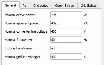
Tab: "1 - General"
In this component tab, the general parameters of the PV and the grid can be specified.
| Parameter | Code name | Description |
|---|---|---|
| Nominal active power | Pnom | PV Power Plant nominal active power. [W] |
| Nominal apparent power | Snom | PV Power Plant nominal apparent power. [VA] |
| Nominal converter line voltage | Vnom_LL | PV Power Plant nominal line voltage (transformer's primary side). [V] |
| Nominal frequency | fnom | PV Power Plant nominal frequency . [Hz] |
| Include transformer | include_transformer | Include the transformer in the PV Power Plant power stage model. |
| Nominal grid line voltage | Vnom_sec_LL | Nominal line voltage of the grid (transformer's secondary side). [V] |
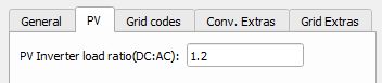
Tab: "2 - PV"
In this component tab, parameters that are related to the PV side of the converter can be specified.
| Parameter | Code name | Description |
|---|---|---|
| PV Inverter load ratio (DC:AC) | ILR_factor | Factor that determines the ratio of the power that PV panels are capable of producing (DC) at STC (standard test condition - 25ºC and 1000W/m2) and nominal power of the inverter (AC). |
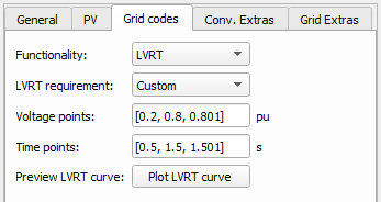
Tab: "3 - Grid codes"
In this component tab, different Grid code parameters can be specified. Currently, LVRT (Low Voltage Ride Through), VoltVAr, HzWatt, and VoltWatt functionalities are supported.
| Parameter | Code name | Description |
|---|---|---|
| LVRT requirement | lvrt_req | Automatically parametrizes voltage and time points according to the chosen requirements. If the Custom option is selected, voltage and current points become available for editing. |
| Voltage points | vs_lvrt | LVRT curve voltage points. [pu] |
| Time points | ts_lvrt | LVRT curve time points. [s] |
| Preview LVRT curve | preview | Displays the created LVRT curve. |
Implementation details for the LVRT unit are given on the LVRT in generic DER components page.
| Parameter | Code name | Description |
|---|---|---|
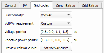
| VoltVAr requirement | voltvar_req | Allows for defining voltage and reactive power points. Currently, only the Custom option is supported. |
| Voltage points | vs_voltvar | VoltVAr curve voltage points. |
| Reactive power points | qs_voltvar | VoltVAr curve reactive power points. |
| Preview VoltVAr curve | preview_voltvar | Displays the created VoltVAr curve. |
If LVRT and VoltVAr functionalities are both enabled, then the VoltVAr curve has priority over the LVRT reactive power contribution setting (Q_contribution).
The VoltVAr curve is linearly extrapolated for voltage values below and above the minimum and maximum values. Also, the curve is limited by a maximum value of reactive power which can be produced or stored. This limit is calculated as , where opc_pu is the overpower capability.
| Parameter | Code name | Description |
|---|---|---|
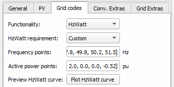
| HzWatt requirement | hzwatt_req | Allows for defining frequency and active power points. Currently, only the Custom option is supported. |
| Frequency points | fs_hzwatt | HzWatt curve frequency points. |
| Active power points | ps_hzwatt | HzWatt curve active power points. |
| Preview HzWatt curve | preview_hzwatt | Displays the created HzWatt curve. |
If LVRT and HzWatt functionalities are both enabled, then the HzWatt curve has priority over the LVRT active power contribution setting.
If the frequency value is below the minimum value or above the maximum value, then the Grid frequency out of range error will appear. The HzWatt curve is limited by a maximum value of active power which can be produced. This limit is calculated as , where opc_pu is the overpower capability.
| Parameter | Code name | Description |
|---|---|---|
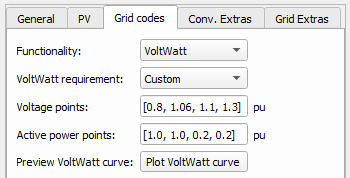
| VoltWatt requirement | voltwatt_req | Allows for defining voltage and active power points. Currently, only the Custom option is supported. |
| Voltage points | vs_voltwatt | VoltWatt curve voltage points. |
| Active power points | ps_voltwatt | VoltWatt curve active power points. |
| Preview VoltWatt curve | preview_voltwatt | Displays the created VoltWatt curve. |
If LVRT and VoltWatt functionalities are both enabled, then the VoltWatt curve has priority over the LVRT active power contribution setting. But, if HzWatt and VoltWatt functionalities are both enabled, then the HzWatt curve has priority over the VoltWatt curve.
The VoltWatt curve is linearly extrapolated for voltage values below and above the minimum and maximum values. Also, the curve is limited by a maximum value of active power which can be produced. This limit is calculated as , where opc_pu is the overpower capability.
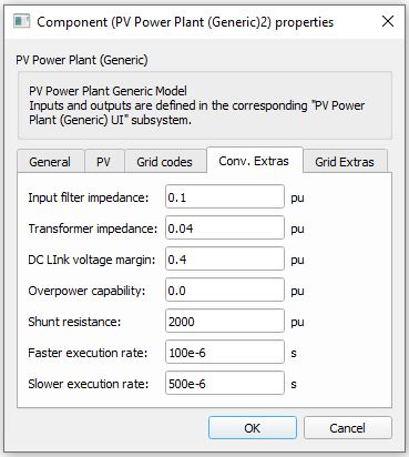
Tab: "4 - Conv. Extras"
In this component tab, the additional parameters that are related to the converter can be specified.
| Parameter | Code name | Description |
|---|---|---|
| Input filter impedance | wL_pu | Input filter impedance. Input filter is a simple L type filter. See the PV Power Plant (Generic) power stage image. [pu] |
| Transformer impedance | Zt_n | Determines the transformer impedance. The position of this transformer is shown in PV Power Plant (Generic) power stage image. [pu] |
| DC link voltage margin | dc_link_margin | Voltage margin over the minimal allowed DC link voltage. This value restricts the maximum voltage that a converter can generate. [pu] |
| Overpower capability | opc_pu | Determines the overpower capability of the converter. [pu] |
| Shunt resistance | Rshunt_pu | The value of the shunt resistances that are used for the measurement of phase voltages at the converter input. The position of shunts is shown in PV Power Plant (Generic) power stage image. [pu] |
| Faster execution rate | Tfast | The Faster execution rate at which part of the inner signal processing of the component will be executed. Should be approximately 5 to 10 times faster than the Slower execution rate. [s] |
| Slower execution rate | Tslow | The Slower execution rate, at which part of the inner signal processing of the component will be executed. This execution rate is inherited by the connected UI subsystem. Should be approximately 5 to 10 times slower than the Faster execution rate. [s] |
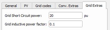
Tab: "5 - Grid Extras"
In this component tab, additional parameters that are related to the grid can be specified.
| Parameter | Code name | Description |
|---|---|---|
| Grid Short Circuit power | Sg_sc_pu | Short circuit apparent power of the grid that the converter is connected to. This parameter doesn't influence the power stage of the model, only the control part. Stable operation of the converter can be achieved by tuning this parameter. [pu] |
| Grid inductive power factor | PFg | Power factor of the grid that the converter is connected to. This power factor occurs when the grid is short-circuited. This parameter doesn't influence the power stage of the model, only the control part. Stable operation of the converter can be achieved by adjusting this parameter. [pu] |
Example
Overall behavior and control methodologies can be better understood with the use of the given example:
Model name: pv_plant_gen.tse
SCADA interface: SCADA_Panel.cus
Path: /examples/models/microgrid/pv_plant//pv_plant (generic)