ABB Powerlink
Description of ABB Powerlink protocol implementation in the Typhoon HIL toolchain.
ABB Powerlink in the Typhoon HIL toolchain
Powerlink is an ABB proprietary communication protocol allowing real time deterministic communication between various ABB controllers. The Typhoon HIL implementation of the ABB Powerlink protocol works over GPIO pins on the HIL device. The number of channels is configurable, up to a maximum of four channels per device. ABB Powerlink protocol is supported on the following Typhoon HIL devices: HIL101, HIL404, HIL506, and HIL606.
| Component | Dialog window |
|---|---|
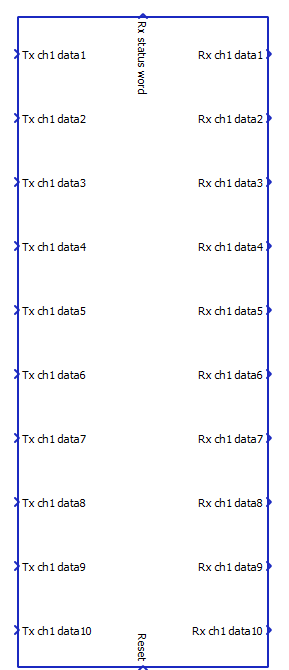 |
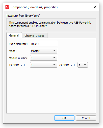  |
| Port | Description |
|---|---|
| Tx ch data | 16 bit data to be transmitted. |
| Rx ch data | 16 bit data to be received. |
| Rx status word | Each channel has two status bits:
Possible status values:
|
| Reset | Resets the component when set to 1. |
| Parameter | Description |
|---|---|
| Execution rate | Signal processing execution rate. |
| Mode | Choice between Master and Slave mode. |
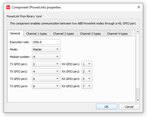
| Module number | Number of Powerlink channels. |
| TX/RX GPIO pins | Configure which GPIO pins map to Powerlink TX and RX. |
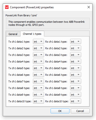
| Channel types | Data type choice for every TX and RX data value. |
Connectivity
In order to connect the HIL device to the Powerlink network, optical converters are used. Converters are connected to the HIL GPIO, converting HIL input and output signals to optical signals, as shown in Figure 1 and Figure 2.
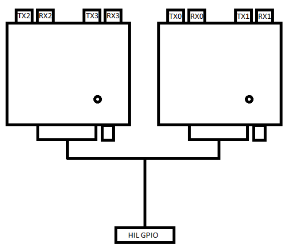
The order of hardware connections inside the converter GPIO connector shown in Figure 2 is as follows:
- GPIO 1 → RX0
- GPIO 2 → TX0
- GPIO 3 → RX1
- GPIO 4 → TX1
- GPIO 5 → RX2
- GPIO 6 → TX2
- GPIO 7 → RX3
- GPIO 8 → TX3