SunSpec Modbus Device
Description of the SunSpec Modbus device in Schematic Editor
SunSpec Modbus
The SunSpec Alliance is a trade alliance of developers, manufacturers, operators and service providers, together perusing open information standards for distributed energy industry. The Information Models can be used to convey device data between any two communicating entities by mapping them to the communication protocol appropriate for the entities. The Modbus mapping is used in Typhoon HIL toolchain, hence the SunSpec Modbus name
- Common Model
- Standard Models
- Vendor Models
- End Model
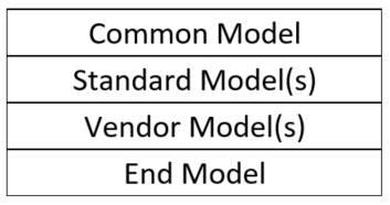
A device definition is a collection of three or more information models: a Common Model, one or more Standard or Vendor Models and an End Model as shown below. Each Information Model is uniquely defined and contains a well-known identifier and length. End Model is a special Model that signalizes the end of a SunSpec configuration.
Each model consists of different number of registers with the different addresses, types and length. All registers in the SunSpec model comprise a register map. All SunSpec devices maps begin with one of the well-known base addresses and start with the well-known 32-bit ‘SunS’ identifier (0x53756e53). This allows for the discovery of SunSpec compatible devices. There are three values for base addresses:
- Preferred Base Register: 40001
- Alternate Base Register: 50001
- Alternate Base Register: 00001
For example, to read register 40001, use hexadecimal offset of 0x9C40 (40000) on the wire.
For additional information about the SunSpec Information model, consult SunSpec Information Model Specification document available on the official SunSpec Alliance web page (https://sunspec.org/)
SunSpec Modbus Device component in Typhoon HIL toolchain
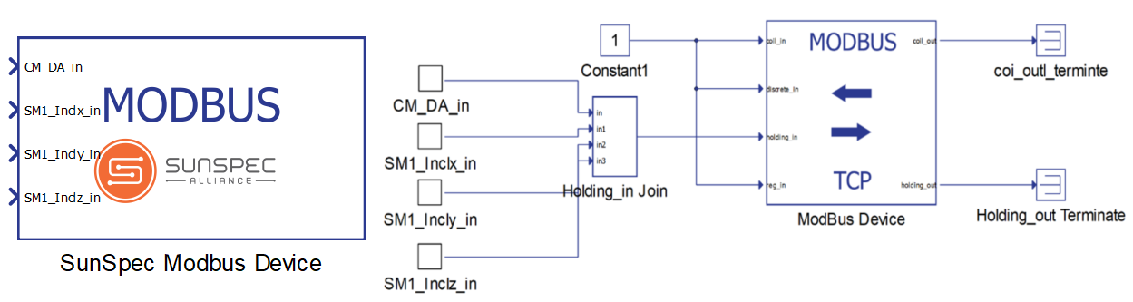
SunSpec Modbus Device component in Typhoon HIL Schematic Editor is primarily based on using Modbus device component to establish Modbus communication with the client. SunSpec Modbus Device component can be viewed as a graphical interface for creating configuration for Modbus component in a way that the Modbus server is SunSpec compatible. SunSpec Modbus Device component is developed as a subsystem with the Modbus Device component underneath. Figure 2 illustrates an under the hood look of this component.
After opening a components dialog window (SunSpec Modbus Device dialog window), two parts of the server can be defined, the communication part and the register part.
For the communication part, the IP, Netmask and Port can be defined. Additionally, there is an option for which ethernet port on the back of the HIL device is used for communication. For 4th generation devices (HIL101, HIL404, HIL506, and HIL606), any available port can be used for communication, while older devices only support communication over port 1.
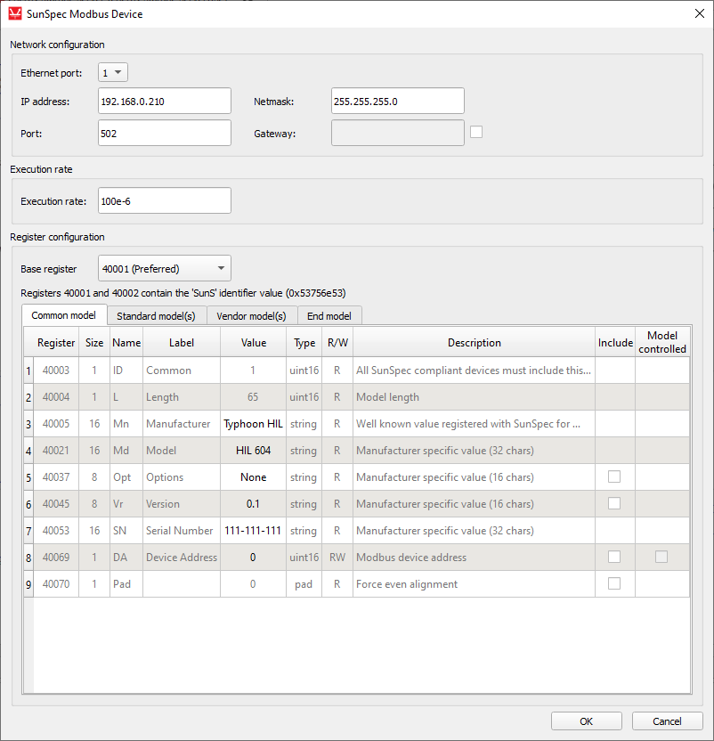
Registers of the Common model are automatically created and are predefined.
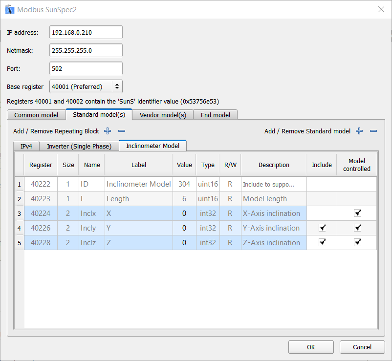
After switching to Standard Model(s) tab, you can specify what Standard Models the server will support. Clicking the Add Standard Model button, a list of all Standard Models will be presented where a specific model(s) can be selected. Each selected model appears as a separate tab (Figure 4).
If the Standard Model has a repeating register block, Add/Remove Repeating Block buttons will appear. With these buttons repeating blocks can be added and removed for the model.
The order of the models can be easily changed by dragging and dropping a model tab to the desired position. The register addresses will be automatically updated.
Vendor Model(s) tab is the same as Standard Model(s) tab with the difference that after clicking the Add Vendor Model button, a browser window will be presented where any vendor model (with ID between 65000 and 65535) can be imported.
After the register map is configured, on OK button, validation of the initial values will occur and if the validation passes, a configuration is created and written in the configuration property of Modbus Device component.
Time synchronization
If there is a need for time synchronization, please take a look at Time synchronization.Virtual HIL support
Virtual HIL currently does not support this protocol. When using a non-real-time environment (e.g. when running the model on a local computer), inputs to this component will be discarded and outputs from this component will be zeroed.