CAN Bus protocol
Description of the CAN Bus protocol implementation in the Typhoon HIL toolchain.
CAN Bus protocol introduction
The Controller Area Network protocol (CAN or CAN Bus) is a two-wire (twisted-pair), bidirectional serial bus communication method that allows electronic subsystems to be linked together and interact in a network.
- The physical layer uses differential transmission on a twisted pair wire
- A non-destructive bit-wise arbitration is used to control access to the bus
- The messages are small (at most eight data bytes) and are protected by a checksum
- There is no explicit address in the messages; instead, each message carries a numeric value which controls its priority on the bus and may also serve as an identification of the contents of the message
- An elaborate error handling scheme that results in retransmitted messages when they are not properly received
- There are effective means for isolating faults and removing faulty nodes from the bus
CAN Bus has a multi-master capability meaning any node on the bus can initiate communication to any other node in a network.
All nodes on the CAN network must operate at the same nominal bit rate otherwise errors will occur on receiving side.
CAN specifications are international standards. Two versions are now in use: CAN 2.0A, the low-speed version, sometimes known as Basic or Standard CAN, is defined by the ISO11519 standard; CAN 2.0B, the high-speed version, also known as Full CAN or extended-frame CAN, is defined by the ISO11898 standard
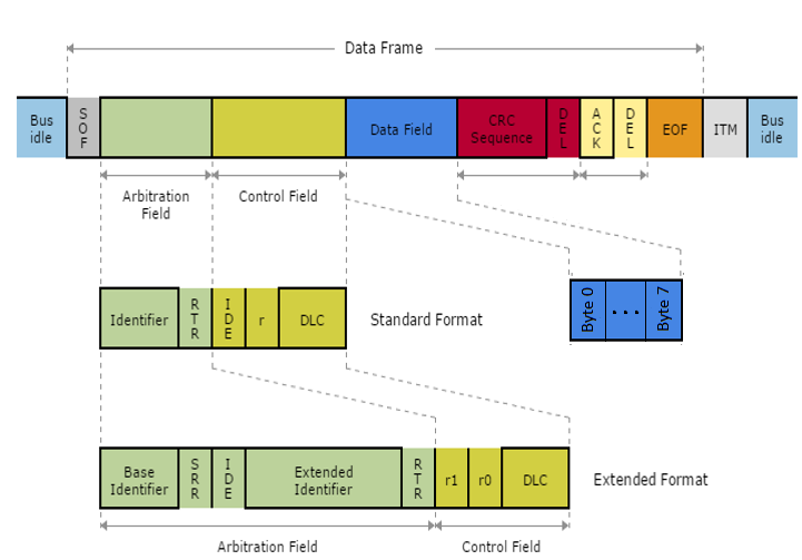
Two or more nodes are required on the CAN Bus network to communicate. A message, or Frame, consists primarily of the ID (identifier), which represents the priority of the message, and up to eight data bytes. A CRC, an acknowledge slot (ACK), and other overhead are also part of the message. CAN Bus message frame is shown in Figure 1.
Messages are labeled by an identifier (ID) assigned to one or more nodes on the network. All nodes receive the message and perform a filtering operation. That is, each node executes an acceptance test on the identifier to determine if the message, and thus its content, is relevant to that particular node. Only the node(s) for which the message is relevant will process it. All others ignore the message.
The identifier has two more functions, as well. It contains data that specifies the priority of the message and it allows the hardware to arbitrate for the bus. That is, it’s used to determine which node gets to transmit if several nodes attempt to do so simultaneously. Message IDs must be unique in a single CAN Bus network, otherwise two nodes would continue transmission beyond the end of the arbitration field (ID) causing an error. The lower the numerical ID, the higher the message priority.
Up to 8 bytes of data can be transmitted through a single CAN Bus message. DLC field, or Data Length Code, tells how many bytes of data are present in the Data Field.
A DLC value of 0 indicates a special type of message frame called Remote Frame. Remote frames are used to request data from a specific node inside the network and these frames do not carry any information. If a node receives a Remote frame with the correct ID, that node will automatically send its data through a network.
CAN Bus protocol in Typhoon HIL toolchain
Currently, CAN Bus functionality in Typhoon HIL is implemented either directly on the HIL device (supported by the following Typhoon HIL devices: HIL101, HIL404, HIL602+, HIL604, HIL506, and HIL606) or through the ACE board (Automotive Communication Extender).
Each currently supported HIL device has two separate CAN controllers, with separate connectors, running on a 100 MHz reference clock. These two controllers (referenced as CAN1 and CAN2) can be connected to the CAN Bus network through a standard 9-pin D-sub type male connector.
Information regarding the available ports for each HIL Simulator device is documented in their respective General Specifications section. The pinout for the CAN connector per HIL device is available here:
The connector pinout for the CAN controllers on the ACE board is described here: Automotive Communication Extender card pinouts.
CAN controllers on HIL devices are not terminated with any resistors. 120 Ohm termination resistors should be added as needed.
CAN controllers on the ACE board are terminated with 120 Ohm resistors.
Depending on whether the CAN controller is on the HIL device or the ACE board, each CAN controller can be configured using either the CAN Bus Setup component or the ACE CAN Setup component.
Each CAN controller can be used to receive and transmit messages. CAN Bus Send and CAN Bus Receive components are used to define sending and receiving of messages.
Although sending and receiving of 64 bit data is supported in the CAN Bus protocol, all registers in a HIL device are 32 bit long so the received data will be converted to 32 bit and sending of 64 bit data will be equal of sending the 32 bit data.
Also, it is important to mention that handling of Remote frames is currently not supported.
CAN Bus over CAN FD controller
HIL devices that have CAN FD controllers (currently HIL506 and HIL606) can be configured so that these controllers behave as regular CAN Bus controllers, thus doubling the CAN Bus capabilities.
- Additional tabs for defining controller parameters
- Two new outputs: can fd1 and can fd2
Additionally, CAN FD1 and CAN FD2 values will appear as options for CAN controller selection in CAN Bus Send and CAN Bus Receive components.
CAN Bus Setup
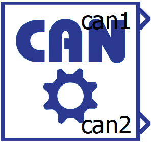
The CAN Bus Setup component is shown in Figure 2. Each currently supported HIL device has two CAN controllers (referenced as CAN1 and CAN2), and the CAN Bus Setup component is used to configure these controllers for each HIL device used in the model.
If CAN protocol is used, there must be exactly one CAN Bus Setup component in the model for each HIL device that uses CAN protocol.
- General (Tab)
- Execution rate
- Signal processing execution rate. Execution rate must match with the other components used in the model.
- Execution rate
- CAN (FD)x (Tab)
- Specify bit timing values for CAN(FD)x
- The bit timing constants (Clock Divider, Time Segment 1,
Time Segment 2 and Resynchronization Jump Width) can be
specified in two ways:
- Automatic - bit timing constants are calculated automatically using the specified baud rate and the controller's reference clock of 100 MHz. The values are calculated so that the number of time quante is in range of 8 - 25, sample point is around 85%, and Resynchronization Jump Width is 4.
- Manual - bit timing constants are set manually.
Note: If you are not familiar with the concept of CAN bit timing, it is highly recommended to keep this value set to Automatic.
- The bit timing constants (Clock Divider, Time Segment 1,
Time Segment 2 and Resynchronization Jump Width) can be
specified in two ways:
- CAN (FD)x baud rate
- Available if Specify bit timing values for CAN (FD)x is set to Automatic.
- Baud rate value for controller x.
- CAN (FD)x Clock Divider
- Available if Specify bit timing values for CAN (FD)x is set to Manual.
- Specifies the Clock Divider constant for bit timing.
- CAN (FD)x Time Segment 1
- Available if Specify bit timing values for CAN (FD)x is set to Manual.
- Specifies the Time Segment 1 constant for bit timing.
- CAN (FD)x Time Segment 2
- Available if Specify bit timing values for CAN (FD)x is set to Manual.
- Specifies the Time Segment 2 constant for bit timing.
- CAN (FD)x Resynchronization Jump Width
- Available if Specify bit timing values for CAN (FD)x is set to Manual.
- Specifies the Resynchronization Jump Width constant.
- CAN (FD)x execution rate
- Execution rate at which the sending of messages is executed for controller x.
- Specify bit timing values for CAN(FD)x
- The CAN Setup component features multiple status
outputs:
- can1 and can2 - indicating the status of CAN1 and CAN2 controllers.
- can fd1 and can fd2 - additional outputs that appear when the HIL device with CAN FD capabilities is selected, indicating the status of CAN FD1 and CAN FD2 controllers.
- These statuses serve to indicate whether any errors occurred during the communication process or if certain buffer conditions are present.
- Each status corresponds to a specific bit in a binary number that is set when the condition occurs and cleared when the condition is resolved. Status bits are numbered from 0 (least significant bit) to 7 for CAN1/CAN2 controllers, or 0 to 8 for CAN FD1/CAN FD2 controllers, where bit 0 corresponds to position xxxx xxx1:
- xxxx xxx1 - ACK Error - No acknowledgement received during frame transmission.
- xxxx xx1x - Bit Error - Transmitted bit value differs from monitored bit value on bus.
- xxxx x1xx - Stuff Error - More than five consecutive identical bits detected during transmission.
- xxxx 1xxx - Form Error - Frame format violation in fixed-form fields.
- xxx1 xxxx - CRC Error - CRC mismatch indicating data corruption during transmission.
- xx1x xxxx - Bus Off - Controller disconnected from bus due to excessive errors.
- x1xx xxxx - RX FIFO Overflow - Receive buffer full, incoming message lost.
- 1xxx xxxx - TX FIFO Full - Transmit buffer full, cannot queue additional messages.
- 1 xxxx xxxx - TX FIFO Transmitting - This occurs when attempting to send a new message while a previous transmission is in progress. New messages are queued if FIFO space is available, otherwise they are discarded to prevent data corruption. This status is only available for CAN FD1 and CAN FD2 controllers.
ACE CAN Setup
The ACE CAN setup component is shown in Figure 3. It is used for configuring the CAN/CAN FD controllers located on the Automotive Communication Extender.
- General (Tab)
- Device ID
- Choose the Device ID corresponding to the ACE board for which the settings apply.
- Ethernet port
- Choose the Ethernet port to which the ACE board is connected.
- Execution rate
- Signal processing execution rate. Execution rate must match with the other components used in the model.
- CANx protocol type
- Choose between the CAN and CAN FD protocol types.
- Depending on the selected protocol, the option to select ACEy - CANx controllers (where y is the value of the chosen Device ID) will be available in either the CAN Bus Send and Receive components or the CAN FD Send and Receive components.
- Specify bit timing values for CANx
- The bit timing constants (Clock Divider, Time Segment 1,
Time Segment 2 and Resynchronization Jump Width) can be
specified in two ways:
- Automatic - bit timing constants are calculated automatically using the specified baud rate and the controller's reference clock of 100 MHz. The values are calculated so that the number of time quante is in range of 8 - 25, sample point is around 85%, and Resynchronization Jump Width is 4.
- Manual - bit timing constants are set manually.
Note: If you are not familiar with the concept of CAN bit timing, it is highly recommended to keep this value set to Automatic.
- The bit timing constants (Clock Divider, Time Segment 1,
Time Segment 2 and Resynchronization Jump Width) can be
specified in two ways:
- CANx baud rate
- Available if Specify bit timing values for CANx is set to Automatic.
- Baud rate value for controller x.
- CANx Clock Divider
- Available if Specify bit timing values for CANx is set to Manual.
- Specifies the Clock Divider constant for bit timing.
- CANx Time Segment 1
- Available if Specify bit timing values for CANx is set to Manual.
- Specifies the Time Segment 1 constant for bit timing.
- CANx Time Segment 2
- Available if Specify bit timing values for CANx is set to Manual.
- Specifies the Time Segment 2 constant for bit timing.
- CANx Resynchronization Jump Width
- Available if Specify bit timing values for CANx is set to Manual.
- Specifies the Resynchronization Jump Width constant.
- Device ID
- Status output on all ACE Setup components indicates:
- Backward compatibility - During the configuration phase of the ACE card,
a backward compatibility check is executed to validate if the
firmware of the ACE card and the firmware of the HIL setup are in agreement.
Depending on the validity of the two firmwares, the first two bits of the status
output are set/reset.
- xxxx xxx1 - Valid firmwares on both THCC (Typhoon HIL Control Center) and ACE side.
- xxxx xx1x - Firmware on either ACE or HIL is not valid. Update THCC and ACE firmware version.
- Configuration errors - If configuration of some of the ACE
protocols is not applied successfully, the corresponding bit will be
set.
- xxxx x1xx - CAN protocol is not configured properly.
- xxxx 1xxx - SPI protocol is not configured properly.
- xxx1 xxxx - LIN protocol is not configured properly.
- xx1x xxxx - SENT protocol is not configured properly.
- If any available protocol reports a configuration error, simply reboot the ACE card and reload the SCADA simulation.
- Backward compatibility - During the configuration phase of the ACE card,
a backward compatibility check is executed to validate if the
firmware of the ACE card and the firmware of the HIL setup are in agreement.
Depending on the validity of the two firmwares, the first two bits of the status
output are set/reset.
- The comm_err output on ACE CAN Setup provides a vector output with
dimension 8, where each of those outputs represent a communication error
on the corresponding ACE CAN controller (output index matches the ACE
CAN controller index). Errors for each ACE CAN controller can
indicate:
- Nominal Phase Errors (bits 0-6):
- xxxx xxxx xxxx xxx1 - NACK Error - No acknowledgement received during nominal bit rate phase.
- xxxx xxxx xxxx xx1x - NBIT0 Error - Recessive bit transmitted but dominant bit monitored during nominal phase.
- xxxx xxxx xxxx x1xx - NBIT1 Error - Dominant bit transmitted but recessive bit monitored during nominal phase.
- xxxx xxxx xxxx 1xxx - NSTUFF Error - Bit stuffing violation during nominal bit rate phase.
- xxxx xxxx xxx1 xxxx - NFORM Error - Frame format violation during nominal bit rate phase.
- xxxx xxxx xx1x xxxx - NCRC Error - CRC mismatch during nominal bit rate phase.
- xxxx xxxx x1xx xxxx - TXBO Error - Controller disconnected from bus due to excessive errors.
- Data Phase Errors (bits 7-11):
- Bit monitoring mismatch:
- xxxx xxxx 1xxx xxxx - DBIT0 Error - Recessive bit transmitted but dominant bit monitored during data phase.
- xxxx xxx1 xxxx xxxx - DBIT1 Error - Dominant bit transmitted but recessive bit monitored during data phase.
- xxxx xx1x xxxx xxxx - DSTUFF Error - Bit stuffing violation during data bit rate phase.
- xxxx x1xx xxxx xxxx - DFORM Error - Frame format violation during data bit rate phase.
- xxxx 1xxx xxxx xxxx - DCRC Error - CRC mismatch during data bit rate phase.
- Bit monitoring mismatch:
- Error State and Buffer Statuses (bits 12-15):
- 1xxx xxxx xxxx xxxx - TX FIFO Transmitting - This occurs when attempting to send a new message while a previous transmission is in progress. New messages are queued if FIFO space is available, otherwise they are discarded to prevent data corruption.
- Nominal Phase Errors (bits 0-6):
CAN Bus Send

The CAN Bus Send component is shown in Figure 4. It is used to specify the format and values of a single CAN message to be sent.
- CAN controller
- Choose which controller sends the message. CAN1 and CAN2 are the default options for message transmission.
- If the ACE CAN Setup component with the CAN Bus protocol type is present in the schematic, additional options to select ACEy - CANx controllers will appear (where y is the selected Device ID and x is the index of the CAN Bus controller).
- If a HIL device with CAN FD capabilities is selected, additional CAN FD1 and CAN FD2 options will be available as well.
- Data input
- Choose if the message is defined manually through the Dialog window, or if the message is defined through a Configuration file.
- Configuration file
- Choose a configuration file to parse. The file can be in DBC or ARXML format.
- Choose message
- Choose message from a configuration file to simulate.
- Message ID
- Specifies the message identifier value. The value for the ID can
be in range 0 - 2N - 1, where N is 11 or 29,
depending on the selected ID typeNote: The identifier value must be unique in a CAN network. While it is possible to specify the same ID values for different CAN controllers (both messages transmitted through CAN1 and CAN2 can have the same ID), connecting these controllers to the same network may cause unexpected errors in communication.
- Specifies the message identifier value. The value for the ID can
be in range 0 - 2N - 1, where N is 11 or 29,
depending on the selected ID type
- Identifier type
- Defines the identifier type. Identifier length can be:
- 11 bit (CAN 2.0A) - used to create messages with a standard, 11 bit, identifier
- 29 bit (CAN 2.0B) - used to create messages with an extended, 29 bit, identifier
- Defines the identifier type. Identifier length can be:
- Message length
- Specifies the length of message payload in bytes (8 bits). Length can be in range from 1 to 8.
- Since Remote frames are not supported, a length of 0 is not allowed.
- Transmit message
- Specifies the condition when the message is transmitted. The
condition can be:
- On event - an additional event terminal is created on the component that triggers sending. The event change is checked on the CAN (FD)x execution rate defined in the CAN Bus Setup component.
- On timer - message is transmitted periodically with the specified period time. Period time must be an integer multiplier of the CAN (FD)x execution rate defined in the CAN Bus Setup component.
- Specifies the condition when the message is transmitted. The
condition can be:
- Transmit period
- Available if Transmit message is set to On timer.
- Specifies the period of message sending.
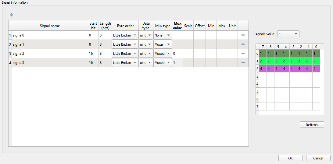
Multiple signals can be transmitted through a single CAN message. With the + (plus) button, a new signal is added to the signal table in the CAN Bus Send dialog window. All signals are packed in one message in the manner defined by the signal parameters. A message preview can be seen on the right of the table, as shown in Figure 5.
- Signal name - name of the signal that is shown on the CAN Bus Send component
- Start bit - the start bit of the signal in CAN message
- Length - length of the signal in bits
- Byte order - represents the byte order of the signal. Signal can be defined as Little or Big Endian
- Data type - signal data type. Signal can be defined as uint, int, or real
- Mux type - choose between None, Muxer, and Muxed to define if multiplexer is used when sending messages. If the type is None, the signal will behave normally and it will always be packed in the message. If the type is Muxer, that signal will be packed in the message, and its value will be used as a multiplexer to determine which Muxed signal will be packed as well. If the type is Muxed, that signal will be packed in the message only when the Muxer value is the same as that signals Mux value.
- Mux value - if the signal is defined as Muxed, the Mux value define when that signal will be packed. Multiple signals can be overlapped and the Mux value will be used to define which signal is packed.
- Scale - define the scale performed on the signal value
- Offset - define the offset performed on the signal value
- Min - define the minimum signal value
- Max - define the maximum signal value
- Unit - define signal units
The Start bit value specifies the position of the signal within the data field of the frame. For signals with a Little Endian byte order, the position of the least significant bit is given. For signals with a Big Endian byte order, the position of the most significant bit is given. The bits are counted in a saw-tooth manner. A more detailed explanation of the data field in the CAN message for Big Endian byte order and Little Endian byte order is given below.
The factor and offset define the linear conversion to convert a signal's coded value into the signal's physical value and vice versa:
coded_value = (physical_value - offset) / scale
physical_value = coded_value * scale + offset
The minimum and maximum define the range of valid physical values of the signal.
After the signals are added to the list, the CAN Bus Send component will appear as shown in Figure 6. The signal ports can be connected to any Signal Processing part of the model.
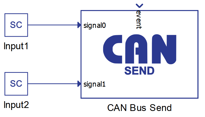
There can be numerous CAN Bus Send components in a schematic, and every such component describes one CAN message to be sent. When adding additional CAN Bus Send components to the model for sending multiple messages, you must ensure that all messages have unique IDs.
CAN Bus Receive

The CAN Bus Receive component is shown in Figure 7. It is used to unpack a message received through a CAN network.
- CAN controller
- Choose which controller receives the message. CAN1 and CAN2 are the default options for message reception.
- If the ACE CAN Setup component with the CAN Bus protocol type is present in the schematic, additional options to select ACEy - CANx controllers will appear (where y is the selected Device ID and x is the index of the CAN Bus controller).
- If a HIL device with CAN FD capabilities is selected, additional CAN FD1 and CAN FD2 options will be available as well.
- Data input
- Choose if the message is defined manually through the Dialog window, or if the message is defined through a configuration file.
- Configuration file
- Choose a configuration file to parse. The file can be in DBC or ARXML format.
- Choose message
- Choose message from a configuration file to simulate.
- Message ID
- Specify the message identifier value. The value for identifier is in range 0 – 2N - 1, where N is 11 or 29, depending on selected identifier type. All messages in the network are filtered and only the message with the identifier value equal to the value defined in the CAN Bus Receive component is parsed.
- Identifier type
- Define the identifier type. Identifier length can be:
- 11 bit (CAN 2.0A) - used to receive messages with standard, 11 bit, identifier
- 29 bit (CAN 2.0B) - used to receive messages with extended, 29 bit, identifier
- Define the identifier type. Identifier length can be:
- Message length
- Specify the length of the payload in bytes (8 bits). Length can be in range from 1 to 8. Since Remote frames are not supported, length of 0 is not allowed.
- Execution rate
- Signal processing execution rate. Execution rate must match with the other components used in the model.
With the + (plus) button, a new signal is added to the signal table in the CAN Bus Receive dialog window. All signals are unpacked in the manner defined by the signal parameters.
Figure 8 shows how the signals can be defined.
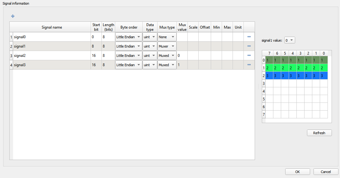
- Signal name - name of the signal that is shown on the CAN Bus Send component
- Start bit - the start bit of the signal in CAN message
- Length - length of the signal in bits
- Byte order - represents the byte order of the signal. The signal can be defined as Little or Big Endian
- Data type - signal data type. Signal can be defined as uint, int, or real
- Mux type - choose between None, Muxer, and Muxed to define if multiplexer is used when decoding messages.
- Mux value - if the signal is defined as Muxed, the Mux value defines when that signal will be unpacked.
- Scale - define the scale performed on the signal value
- Offset - define the offset performed on the signal value
- Min - define the minimum signal value
- Max - define the maximum signal value
- Unit - define signal units
The Start bit value specifies the position of the signal within the data field of the frame. For signals with a Little Endian byte order, the position of the least significant bit is given. For signals with a Big Endian byte order, the position of the most significant bit is given. The bits are counted in the saw-tooth manner. A more detailed explanation of the data field in the CAN message for Big Endian byte order and Little Endian byte order is given below.
The factor and offset define the linear conversion to convert signals coded value into signals physical value and vice versa:
coded_value = (physical_value - offset) / scale
physical_value = coded_value * scale + offset
The minimum and maximum define the range of valid physical values of the signal.
After the signals are added to the list, the CAN Bus Receive component appears as shown in Figure 9. The signal ports can be connected to any Signal Processing part of the model.
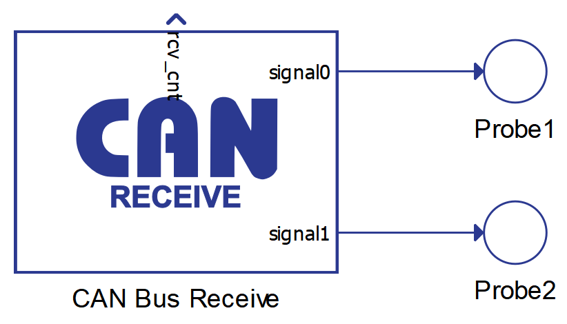
There can be numerous CAN Bus Receive components in a schematic, and every such component is used to receive a CAN message with the defined ID value. Messages that have an ID value that does not mach any ID value defined in CAN Bus Receive components are ignored.
The rcv_cnt value increases by 1 every time a new message is received.
Using configuration files to specify CAN messages
CAN Bus Send/Receive, CAN FD Send/Receive and CAN FD Pack/Unpack components can import DBC or ARXML files to define the messages. The principle is the same for all components and it will be demonstrated only on the CAN Bus Send component.
To load the configuration file, you must choose Configuration file as the Data input property and navigate to the desired file using the Choose file button. If the file is parsed correctly, the Choose message combo box will be populated with the message names from the file. Choosing different messages will change the message and signal parameters in the dialog. An example is shown in Figure 10.
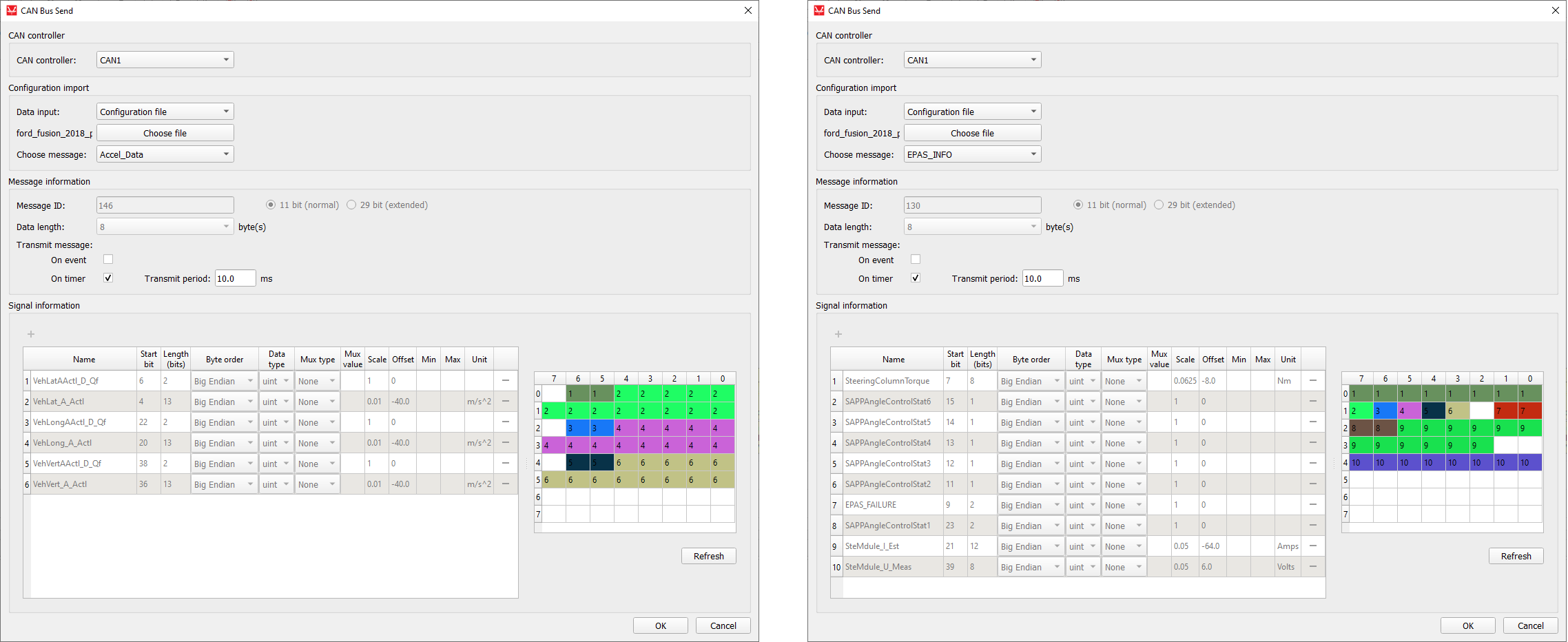
When using DBC or ARXML files to define CAN messages, all message and signal parameters are disabled for editing. If the Data input is changed to Dialog window, the parameters will be enabled for editing, but if the Data input is subsequently changed back to Configuration file, the parameters will be changed back to the values from the configuration file.
Changing component property values using Schematic API
The custom component dialog is designed to easily define CAN message parameters. Changing these values is also possible using standard Schematic API functions but in a modified way. Namely, all properties except Transmit message and Signal information are changed in the standard way, where Transmit message is specified as a Python dictionary type and Request information must be specified as a list of Python dictionary types.
| Field name | Allowed values |
|---|---|
| "On event" | True, False |
| "On timer" | True, False |
| Field name | Allowed values |
|---|---|
| "name" | ASCII string |
| "start_bit" | 0 - 63 |
| "length" | 1 - 64 |
| "byte_order" | "Little Endian", "Big Endian" |
| "data_type" | "int", "uint", "real" |
| "mux_type" | "None", "Muxer", "Muxed" |
| "mux_val" | positive integer |
| "scale" | real number |
| "offset" | real number |
| "min" | real number |
| "max" | real number |
| "unit" | ASCII string |
transmit_type = {
    "On event": True,
    "On timer": False
}
mdl.set_property_value(mdl.prop(can_component, "transmit_type"), transmit_type)

signals = [
    {"name": "signal0", "start_bit": 0, "length": 8, "byte_order": "Little Endian", "data_type": "uint", "mux_type": "None"},
    {"name": "signal1", "start_bit": 8, "length": 8, "byte_order": "Little Endian", "data_type": "uint", "mux_type": "Muxer"},
    {"name": "signal2", "start_bit": 16, "length": 8, "byte_order": "Little Endian", "data_type": "uint", "mux_type": "Muxed", "mux_val": "0"},
    {"name": "signal3", "start_bit": 16, "length": 8, "byte_order": "Little Endian", "data_type": "uint", "mux_type": "Muxed", "mux_val": "1"}
]
mdl.set_property_value(mdl.prop(can_component, "signals"), signals)dbc_file_path = r"C\dbc_files\ford_fusion_2018_pt.dbc"
mdl.set_property_value(mdl.prop(can_component, "file_path"), dbc_file_path)
mdl.set_property_value(mdl.prop(can_component, "choose_message"), "Lane_Keep_Assist_Control")CAN execution rates explained
- Execution rate
- CANx controller execution rate
- CANx baud rate
- Transmit period
This section aims to provide a clarification for each of these values and how they relate to each other.
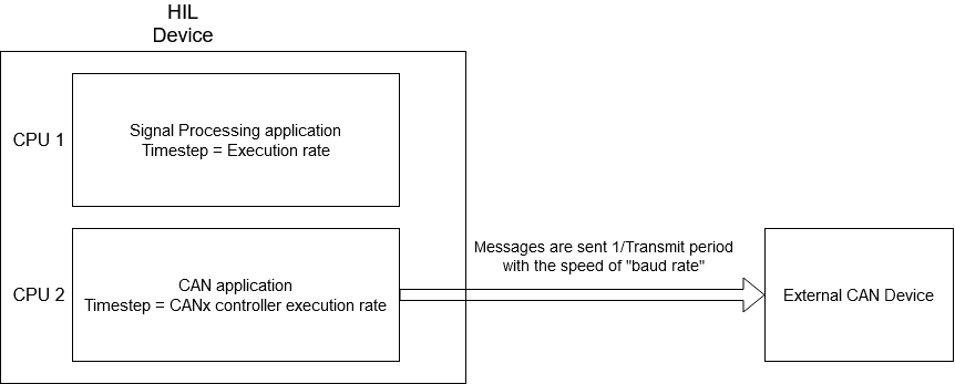
First of all, it is important to distinguish two aspects in all models that use CAN communication protocol: the Signal Processing aspect, and the processing of the CAN communication protocol itself. During model compilation, all Signal Processing components on the schematic are combined in one application that is executed on one CPU core. On the other hand, all CAN components (even though they are a part of the Signal Processing library) are combined in a separate application that is executed on a different CPU core. These two applications are two different entities.
All Signal Processing components (including the CAN components) have the Execution rate property. All components that are connected and perform a logical function share the same execution rate value. The execution rate value defines how often this function is performed.
The CANx controller execution rate has the exact same function, but is specific to the CAN application. It defines how often the CAN function is called.
Each CAN Send component has a Transmit period property that defines how often that message is sent to the network. The Transmit period and the CANx controller execution rate are in direct correlation to each other in a way that the CANx controller execution rate serves as a granularity value for Transmit period. In other words, if the CANx controller execution rate is set to 1 ms, the Transmit period can only be an integer multiple of 1 ms, that is N*1 ms. Similar, if the CANx controller execution rate is set to 3 ms, the Transmit period can only have a value of N*3 ms.
Baud rate is the only value that is defined by the CAN standard. This value is expressed in bits/s and defines how quickly the message is relayed between two CAN controllers. The difference between the Transmit period and the baud rate can be easily illustrated by the example of a metronome. Metronomes periodically makes a click sound (Transmit period), but that click travels by the speed of sound to the listener (baud rate).
Figure 11 illustrates all that was explained above.
Data Field format in the CAN message frame for Big Endian and Little Endian byte order
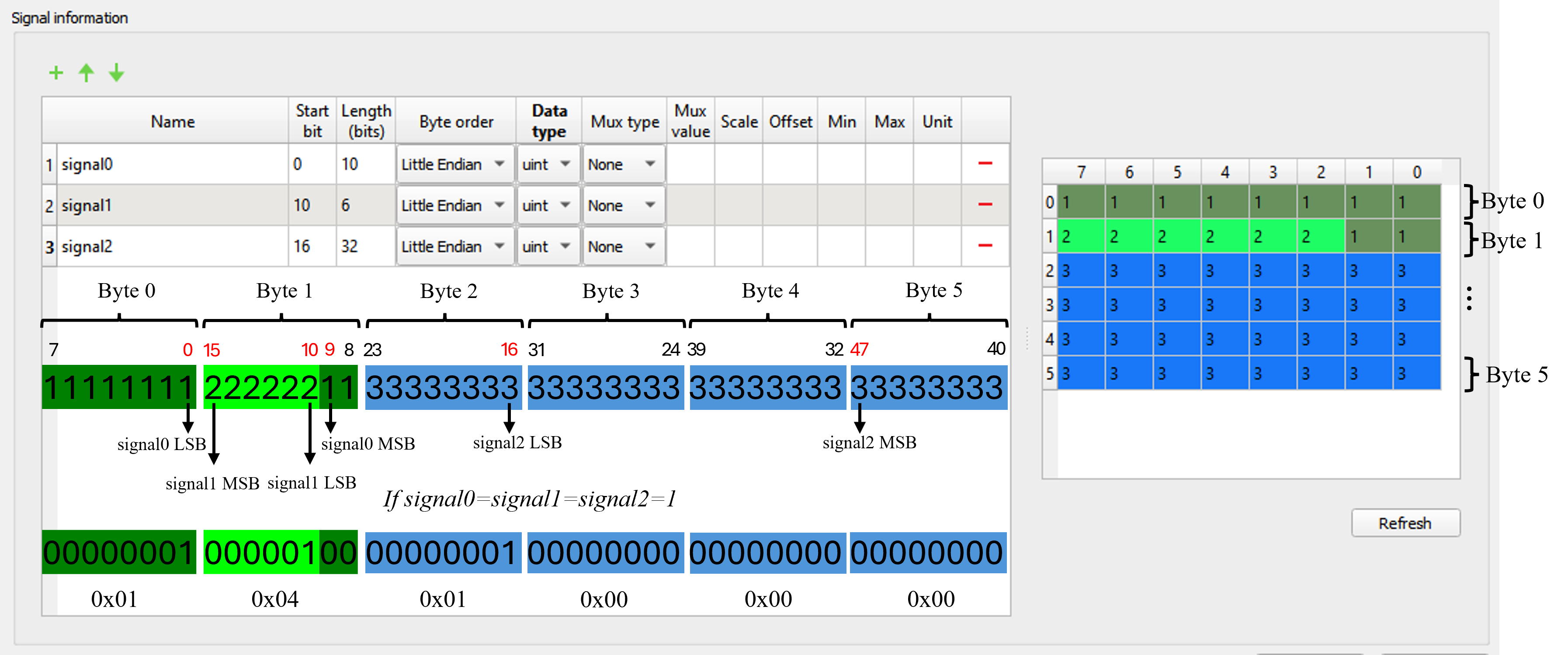
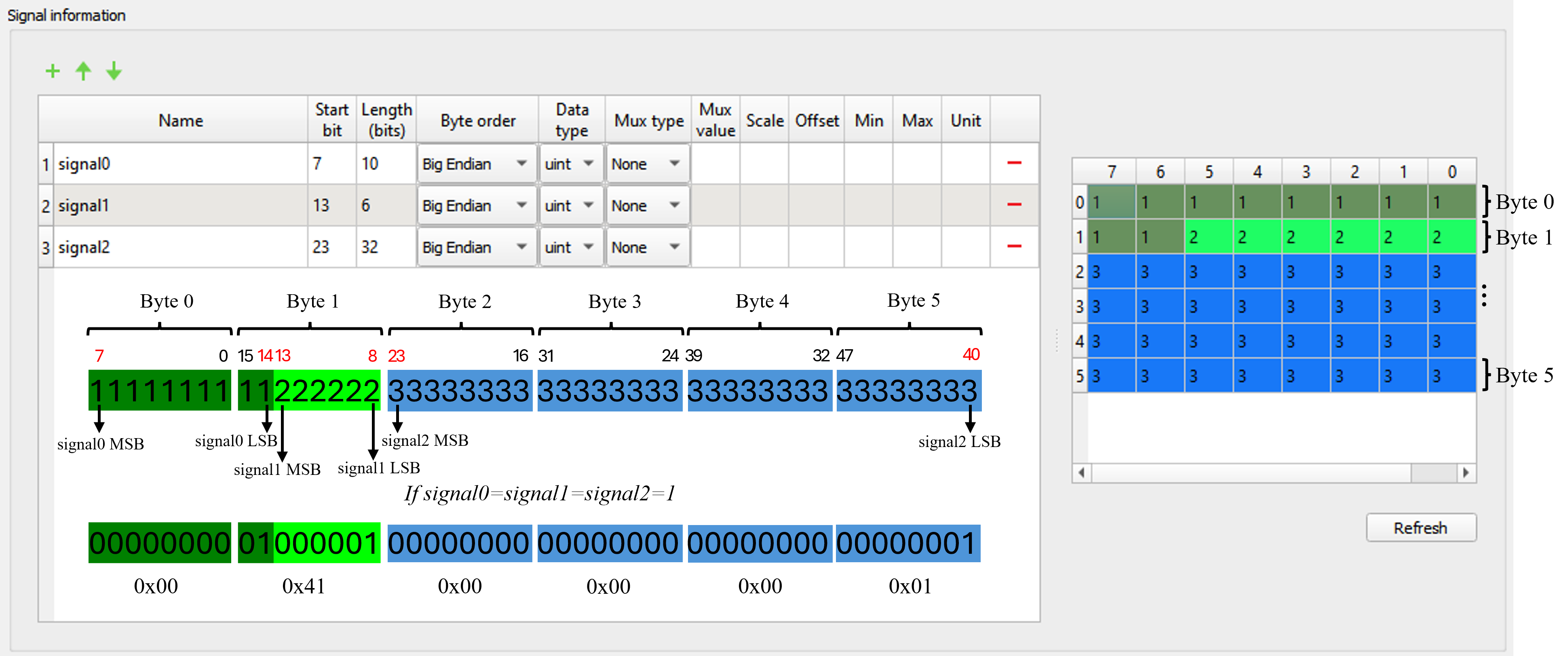
As seen in Figure 1, within one message frame, it is possible to send 8 bytes (from Byte 0 to Byte 7). The Start bit parameter value specifies the position of the signal within the data field of the frame. For Little Endian signals, the start bit corresponds to the least significant bit (LSB) position, while for Big Endian signals, it corresponds to the most significant bit (MSB) position.
In these two examples, illustrated in Figure 12 and Figure 13, the message consists of three signals, but in the first case, they have Little Endian byte order, while in the second case, Big Endian. Depending on whether the signal has Big or Little Endian byte order, it's necessary to set the appropriate start bit for each signal.
By clicking the Refresh button, the arrangements of bits for each signal within the data field section of the CAN message frame is displayed in the table on the right side. Each row of this table represents one data byte of the CAN message, ranging from Byte 0 to Byte 5, as the data length in this example is 6 bytes.
If the signals have a value equal to 1, in the case of Figure 12, the data bytes appearing on the CAN bus in hexadecimal notation are 0x01, 0x04, 0x01, 0x00, 0x00, and 0x00. While in the case of Figure 13, they are 0x00, 0x41, 0x00, 0x00, 0x00, and 0x01.
Virtual HIL support
Virtual HIL currently does not support this protocol. When using a non-real-time environment (e.g. when running the model on a local computer), inputs to this component will be discarded and outputs from this component will be zeroed.