IEC 61850 Sampled Values protocol
Description of the IEC 61850 Sampled Values (SV) protocol implementation in the Typhoon HIL toolchain.
IEC 61850 Sampled Values (SV) protocol
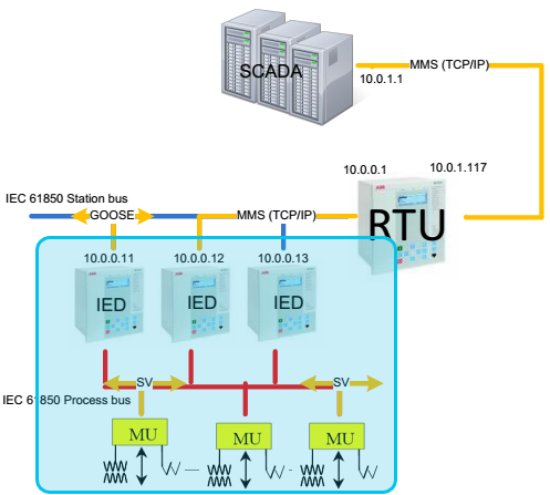
IEC 61850 (IEC 61850 – Communication Networks and Systems in Substations) standard defines Sampled Values (SV) protocol as a publisher/subscriber type communication. This protocol is used for information exchange between Merging Units and IEDs (IED – Intelligent Electronic Device) in a Substation over the Ethernet.
The "Implementation Guidance for Digital Interface to Instrument Transformers Using IEC 61850-9-2", or IEC 61850-9-2LE (LE - Light Edition), guide is used as a reference in the implementation of the SV protocol.
The concept of SV communication is that the publisher periodically sends messages with exactly defined time intervals. The time interval depends on two factors: measured signal frequency and Samples Per Period (SPP). IEC 61850-9-2LE defines two SPP values of 80 and 256. For example, if the measured signal frequency is 50 Hz and SPP is 80, the sending time interval will be 1/50/80, or 250 µs.
All messages are published under a topic. The subscriber receives all messages from the system, but filters and parses only the messages sent with the subscribed topic.
Since the SV protocol is publisher/subscriber based, communication is possible only inside the local network (LAN).
The protocol defines the SV message as shown in Figure 2. The field definition is presented in Table 1.
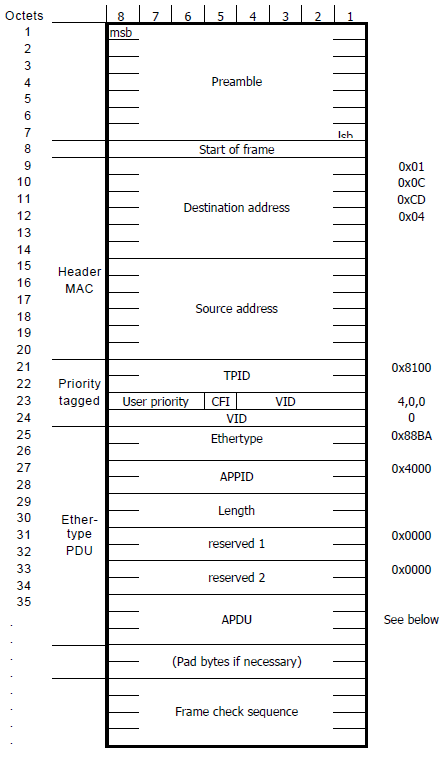
| Field name | Value | Description | ||
|---|---|---|---|---|
|
Destination address 01:0c:cd:04:xx:xx |
00:00 - 01:ff | Destination MAC address | ||
| Source address | Defined by the sending device | Source MAC address | ||
| Priority tagged | TPID | 0x8100 | Defines the 802.1Q protocol | |
| TCI | User priority | 1 - 7 | SV message priority: 4-7 is high priority; 1-3 is low priority | |
| CFI | 0 | Canonical Format Indicator | ||
| VID | 0 - 4095 | Virtual LAN ID | ||
| Ethertype | 0x88ba | Defines the SV protocol | ||
| APPID | 0x4000 - 0x7FFF | Application ID | ||
| Length | Message length | |||
| Reserved 1 | 0x0000 | Reserved field | ||
| Reserved 2 | 0x0000 | Reserved field | ||
| APDU | Application Protocol Data Unit | |||
The structure of Reserved 1 is defined in Figure 3.
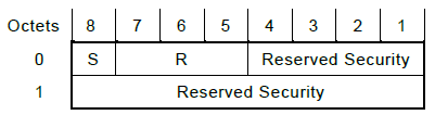
S: Simulate. This flag indicates that the SV message is sent by a test device. This flag helps the Subscriber to distinguish whether the received values are real Voltage and Current values coming from the Merging Units or simulated test values.
R: Reserved. These bits are reserved for future use and are set to 0 by default.
Reserved Security: these four bits and the Reserved 2 field form a 28 bit word defined by the security standard IEC/TS 62351-6. It is used as defined when an SV message with security is transmitted, otherwise it is set to 0.
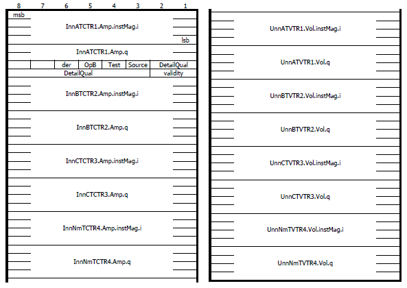
The APDU field contains the payload of the SV messages. Every APDU contains up to 8 ASDU (Application Specific Data Unit), where each ASDU contains one three phase current and voltage measurements and each ASDU has a unique SV identification value. The content of an APDU can be found on Figure 4.
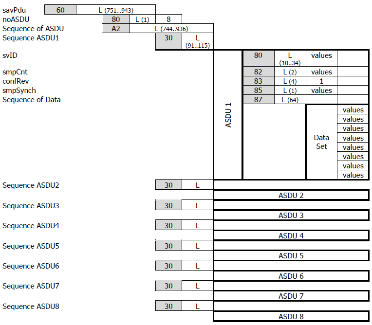
- svID - Sampled Values Identifier, a user-defined unique string identifier used for subscription.
- smpCnt - index of the Sampled Values message
- confRev - configuration revision
- smpSynch - defines the synchronization mechanism of the clock used for sending the SV
messages. The value can be:
- 0 - None
- 1 - Local
- 2 - Global
- Sequence of Data - sequence of measured voltage and current values as shown on Sequence of Data encoding Figure 5.
The guide also defines the scaling factors for current and voltage measurements. Current measurements should be scaled with the factor of 1000 and the voltage with the factor of 100 and written in integer format.
- Validity - formed by concatenating bits 1 and 0 (in that order, with bit 1 as the more
significant bit).
- Good - Value 00 (bit1:bit0)
- Invalid - Value 01
- Reserved - Value 10
- Questionable - Value 11
- Overflow (bit 2)
- False - Value 0
- True - Value 1
- Out of range (bit 3)
- False - Value 0
- True - Value 1
- Bad reference (bit 4)
- False - Value 0
- True - Value 1
- Oscillatory (bit 5)
- False - Value 0
- True - Value 1
- Failure (bit 6)
- False - Value 0
- True - Value 1
- Old data (bit 7)
- False - Value 0
- True - Value 1
- Inconsistent (bit 8)
- False - Value 0
- True - Value 1
- Inaccurate (bit 9)
- False - Value 0
- True - Value 1
- Source (bit 10)
- Process - Value 0
- Substituted - Value 1
- Test (bit 11)
- False - Value 0
- True - Value 1
- Operator blocked (bit 12)
- False - Value 0
- True - Value 1
- Derived (bit 13)
- False - Value 0
- True - Value 1
Sampled Values protocol in Typhoon HIL toolchain
The whole SV protocol is defined by using the following components from the Schematic Editor Library Explorer: SV Setup, SV Publisher and SV Subscriber.
SV Setup

The SV Setup component is used to define SV parameters. If SV protocol is used in the model, there must be exactly one SV Setup component for each HIL device that uses SV protocol.
SV Setup component properties
- Ethernet port
- Choose which Ethernet port will be used for SV protocol.
- Override last digit in MAC address
- Manually specify the last digit of MAC address
- Source device MAC address
- Modify the MAC address of the device. The MAC address of the HIL device is set to 78:72:64:Ax:xx:xy, where 78:72:64:A refers to Typhoon HIL products, x:xx:x is derived by the device's serial number, and y is defined by the selected port value. If Override HIL device ID is selected, you can manually specify the last digit.
- Signal frequency
- Signal frequency of 16.7, 25, 50 and 60 Hz can be selected for each HIL device.
- Samples per period
- 80 and 256 samples per period resolution is defined.
- Enable message quick parse
- This option is used for SV Subscriber components. When the message is first received, the message will be parsed and checked for validity. During parsing, the position of the Sequence of Data field will be saved and used later for faster parsing of the message. If this option is not selected, the message will be parsed every time it is received. It is highly recommended to enable this option if the SV message structure does not change during simulation.
- Execution rate
- Signal processing execution rate. The execution rate must match the other components used in the model.
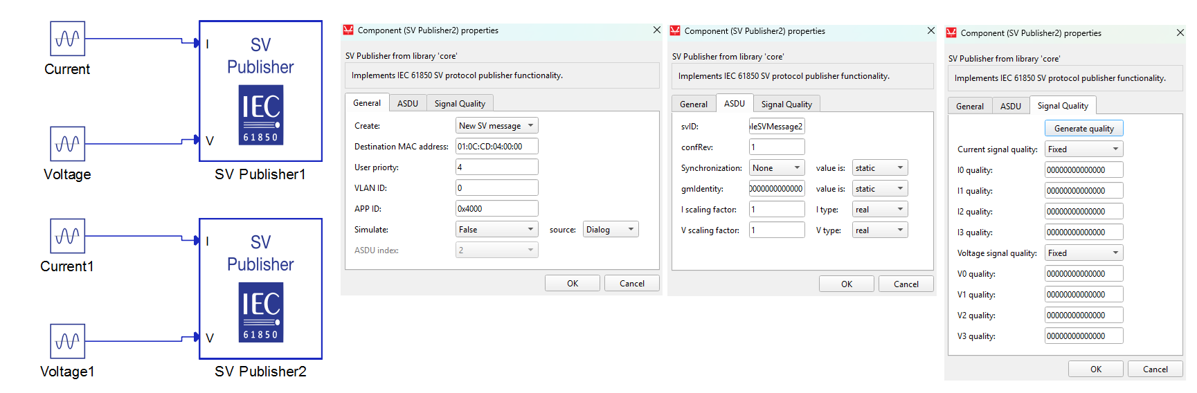
SV Publisher
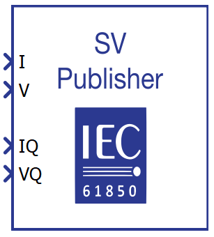
The SV Publisher component is used for specifying parameters for one ASDU field inside the APDU (Figure 4). With each SV Publisher component, you can specify if the component creates a new SV message or if it will add an ASDU in an existing SV message. If the component creates a new SV message, you can specify the destination address, user priority, VLAN ID, and APP ID values.
SV Publisher component properties
- Create
- Choose if the SV Publisher component creates a new SV message with New SV message or if it adds an ASDU to an existing SV message with Sequence ASDU.
- Destination MAC address
- Specify the destination MAC address.
- User priority
- Specify the user priority of the SV message.
- VLAN ID
- Specify the VLAN identifier of the SV message.
- APP ID
- Specify the APP identifier of the SV message.
- Simulate
- Define if the Simulate bit in the Reserved 1 field will be True or False as defined in Figure 3.
- source
- The Simulate value can be defined either through the Dialog window, a signal from the model, or through the SCADA window. If the Dialog option is selected, the Simulate value is fixed and defined through the Simulate property value. If the Model value is selected, an additional terminal will be created on the component that allows you to connect any signal from the model and dynamically change the Simulate value. The SCADA option allows you to define the Simulate value through the SV Publisher.Simulate widget in the SCADA window.
- ASDU index
- Specifies the index of the ASDU index inside the APDU field of SV message. If the New SV message option is selected, ASDU index is fixed to 1. If the Sequence ASDU option is selected, an index from 2 - 8 can be specified.
- svID
- Specify the unique SV identifier for ASDU.
- confRev
- Specify the configuration revision number for ASDU.
- Synchronization
-
Defines if the Synchronization value is fixed and defined using the Synchronization property or if it is dynamically assigned during the simulation. The dynamic value corresponds to the status of the PTP slave running alongside the SV protocol (through the same ethernet port) or the IRIG-B signal received through the dedicated port of that HIL device.
- Available values are dynamic and static.
-
If the PTP Slave is synchronized to the PTP Master clock, the Synchronization value will be either Local or Global depending on the time traceability of the PTP Master's clock. If the PTP Slave is not synchronized, the value will be None.
-
If IRIG-B is used the Synchronization value will be either Global or Local depending on whether the IRIG-B source is locked onto a GPS signal or not.
-
- value is
-
The synchronization value informs the receiver whether the Current/Voltage sampling time is synchronized with the global clock value. Typically, SV senders are synchronized to a global (master) clock in order to relay the exact time the Current/Voltage values are sampled. In this way the the receiver knows if the values are old or up to date, so they can decide whether to accept, discard, or modify the values.
- Available values are None, Local, and Global
-
If the SV sender is synchronized to a master clock (usually using GPS or PTP protocol), the value should be specified as Global.
-
If the SV sender does not have a connection to a master clock but still has a way to synchronize, the value is specified as Local.
-
If the SV sender does not have any means of clock synchronization, the value is specified as None.
-
- gmIdentity
- Specify the source for the gmIdentity field. When static is selected, all publishing messages will contain the gmIdentity field as specified by the property gmIdentity. When dynamic is selected, all publishing SV messages will contain the value identity value of synchronizing the PTP grandmaster clock. When none is selected, publishing SV messages will have no gmIdentity field.
- value is
- Specify the grandmaster identity field value in a publishing SV message. This property is enabled when the value for gmIdentity is set as static.
- Available values are static, dynamic, and none.
- The value must be a hexadecimal number of length 16, specified without the "0x" prefix.
- I scaling factor
- Specify the scaling factor for input current signals. The default scaling for currents is 1000.
- I type
- Defines the current type that is written in the SV message.
- Available values are int, uint, and real.
- For example, if the input current is 1 A and int type is selected, the value 0x0000 0001 will be written in the message. If the real type is selected, the value 0x03f8 0000 will be written.
- V scaling factor
- Specifies the scaling factor for input voltage signals. The default scaling for voltages is 100.
- V type
- Defines the voltage type that is written in the SV message.
- Available values are int, uint, and real.
- For example, if the input voltage is 1 V and int type is selected, the value 0x0000 0001 will be written in the message. If the real type is selected, the value 0x03f8 0000 will be written.
- Generate quality (button)
- Opens a new dialog where you can graphically define the signal quality values. All configurable signal attributes are described here. Useful if the signal quality is set to Fixed.
- Current signal quality
- Choose if the signal quality is specified by signal from the model or is fixed and user defined. If the Variable option is chosen, a port IQ will appear on the component to connect the signal.
- Ix quality
- Available when Current signal quality value is Fixed.
- Allows for manually defining signal quality for each current in binary form.
- Available values are Fixed and Variable.
- Voltage signal quality
- Choose if the signal quality is specified by signal from the model or is fixed and user defined. If the Variable option is chosen, a port VQ will appear on the component to connect the signal.
- Vx quality
- Available when Voltage signal quality value is Fixed.
- Allows for manually defining signal quality for each voltage in binary form.
- Available values are Fixed and Variable.
- Start/Stop SV stream
- Available if Create is set to New SV message.
- This property enables or disables the manipulation of the SV stream published by each SV Publisher, and, if enabled, defines the source of the manipulation control signal.
- If the Model value is selected, an additional terminal called Stop
will be created on the component, allowing the connection of any signal from the
model and the dynamic control of the Start/Stop feature.
This terminal expects an integer value as input. When the value of the signal connected to the Stop terminal is equal to 0, the SV Publisher works as expected. Otherwise, if that value is not equal to 0, the SV stream published by this SV Publisher is stopped.
- The SCADA option allows you to control the manipulation through the SV Publisher.
The stop widget is located in the SCADA window.
The minimum possible value of the widget is 0, and the maximum possible value of the widget is 1. When the widget value is 0, the SV Publisher works as expected. When the widget value is 1, the SV stream published by this SV Publisher is stopped.
SV Publisher examples
An example using SV Publisher components is illustrated in Figure 8. Only one SV Publisher component exists in the model with the parameters defined as shown on the right of the figure. The component creates a new SV message with one ASDU entry where the values are not scaled and are written in real format. The signal quality is fixed and predefined.
All input signals to the SV Publisher component must be vectors of length 4. The vector should be encoded as [I0, I1, I2, I3], [IQ0, IQ1, IQ2, IQ3], [V0, V1, V2, V3], and [VQ0, VQ1, VQ2, VQ3]
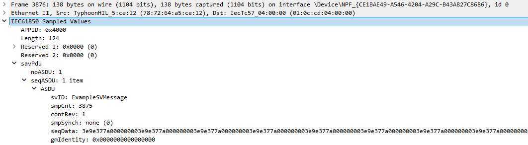
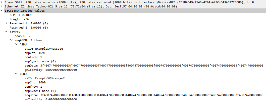
Figure 9 illustrates the message captured with the network sniffing tool.
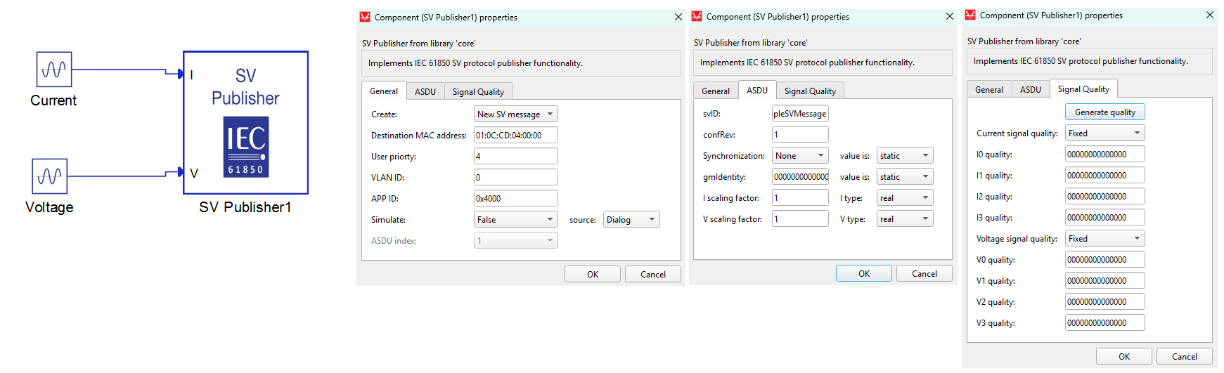
To add an extra ASDU in the existing SV message, just add another SV Publisher component and choose the Create: Sequence ASDU option. This is illustrated in Figure 10. The SV Publisher component is the same as in the example above and creates a new SV message. The SV Publisher1 component is defined to add an ASDU to the message with APP ID 0x4000 as shown on the right of the figure.
A capture of the newly created message is illustrated in Figure 11.
PTP synchronization
The PTP synchronization mechanism ensures that all devices on the network have the same time reference. This time reference is dictated by the Master device on the network, usually called the Grandmaster clock.
Time synchronization of the SV Publishers ensure that they all start counting samples from the same moment in time. In other words, the SV Publishers reset their sample count (smpCnt) value to 0 each time the seconds value is changed (i.e. seconds rollover). This way, a SV Receiver that receives two SV data streams can easily compare the current/voltage values and detect phase shifts.
SV application synchronization using PTP can be achieved by configuring the Time Synchronization component in the following way:
- Select PTP as the synchronization source
- Select the ethernet port used by the SV application
- Select the IEC61850-9-3 predefined PTP configuration
IRIG-B synchronization
The use of this synchronization method is limited to devices with an IRIG-B port. Information regarding the available ports for each HIL Simulator device is documented in their respective General Specifications section.. In order to use IRIG-B synchronization, it is necessary to select "IRIG-B" as the synchronization source in the Time Synchronization component.
Each time the IRIG-B signal is received it resets the sample count (smpCnt) value and updates the internal clock of the HIL device which allows for accurate timestamps in SV Publisher messages.
More information about the IRIG-B signal can be found in the Time synchronization page.
SV Subscriber
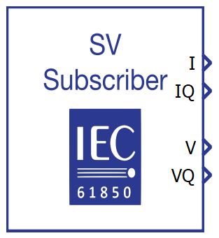
The SV Subscriber component is used for subscribing to a certain ASDU field from a certain SV message on the network. To subscribe to an SV message, the APP ID and SV ID must be specified for message filtering. The APP ID value is used to filter the SV message from the network, and the SV ID is used to extract the corresponding ASDU from the message.
All output terminals of SV Subscriber component are vectors of length 4. The vectors are encoded as [I0, I1, I2, I3], [IQ0, IQ1, IQ2, IQ3], [V0, V1, V2, V3], and [VQ0, VQ1, VQ2, VQ3].
SV Subscriber component properties
- APP ID
- APP ID value for message filtering.
- SV ID
- SV ID for ASDU filtering.
- I scaling factor
- Scaling factor to be applied to current values.
- I type
- Define the current value type which is written in the SV message.
- Available values are int, uint, and real.
- V scaling factor
- Scaling factor to be applied to voltage values.
- V type
- Define the voltage value type which is written in the SV message.
- Available values are int, uint, and real.
- Output smpCnt
- If checked, the smpCnt output appears on the component.
- Output smpCnt is an unsigned integer containing the value parsed from the smpCnt attribute in the received SV message.
- Output smpSynch
- If checked, the smpSynch output appears on the component.
- Output smpSynch is an unsigned integer containing the value parsed from the smpSynch attribute in the received SV message.
- Output Simulate
- If checked, the Simulate output appears on the component.
- Output Simulate is an unsigned integer containing the value parsed from the Simulate attribute in the received SV message. Possible values are 0 and 1, indicating whether a simulation device or a real device published the receiving SV message.
- Execution rate
- Signal processing execution rate. The execution rate must match the other components used in the model.
Virtual HIL support
Virtual HIL currently does not support this protocol. When using a non-real-time environment (e.g. when running the model on a local computer), inputs to this component will be discarded and outputs from this component will be zeroed.