CHAdeMO protocol
Description of the CHAdeMO 1.0 protocol implementation in the Typhoon HIL toolchain.
IEC 61851 standard
In order to understand the CHAdeMO protocol, it is important to first mention the IEC 61851 standard that defines the use of this protocol. This section describes the standard and how CHAdeMO is linked to it.
The IEC 61851 - Electric vehicle conductive charging system [1] standard defines the characteristics of on-board and off-board equipment for charging electric road vehicles at standard AC supply voltages up to 1000 V and at DC voltages up to 1500 V.
- Charging Mode 1 - AC charging, EV to mains over standard 1ph/3ph sockets. Up to 16 A and 250/480 V. No protection device in the charging cable.
- Charging Mode 2 - AC charging, EV to mains over standard 1ph/3ph sockets. Up to 32 A and 250/480 V. Protection device integrated in the charging cable.
- Charging Mode 3 - AC charging using dedicated AC charging stations. Mandatory PWM signaling and optional High Level Communication (HLC)
- Charging Mode 4 - DC charging using dedicated DC charging stations. Mandatory PWM signaling and mandatory High Level Communication (HLC)
- System A - The physical/data layer is through CAN bus A interface while the application layer is defined in IEC 61851-24 standard.
- System B - The physical/data layer is through CAN bus B interface while the application layer is defined by the GB/T 27930 standard.
- System C - The physical/data layer is through Power Line Communication (PLC) while the application layer is defined by the ISO 15118-2 Protocol.
In other words, the CHAdeMO protocol is responsible for defining the digital communication layer between the EV and EVSE for the DC charging mode when System A is applied.
CHAdeMO Protocol
CHAdeMO (Road Vehicles – Vehicle to grid communication interface) [2] is a fast-charging system for battery electric vehicles, developed in 2010 by the CHAdeMO Association, formed by the Tokyo Electric Power Company and five major Japanese automakers.
It competes with the Combined Charging System (CCS), which since 2014 has been required on electric vehicles sold in the European Union, Tesla's North American Charging Standard (NACS) used by its Supercharger network outside of Europe, and China's GB/T charging standard.
First-generation CHAdeMO connectors deliver up to 62.5 kW by 500 V, 125 A direct current through a proprietary electrical connector, adding about 120 kilometres (75 mi) of range in a half an hour. It has been included in several international vehicle charging standards. The second-generation specification allows for up to 400 kW by 1 kV DC at 400 A. The CHAdeMO Association is currently co-developing the third-generation standard that aims to deliver 900 kW with the China Electricity Council (CEC) under the working name of “ChaoJi”. More detailed information on CHAdeMO is defined in IEC 61851-23 ANNEX AA and JIS/TSD0007 [2].
- Physical design: The CHAdeMO connector features a single plug with nine pins arranged in a specific pattern to ensure proper alignment and connection with the vehicle. The connector is designed to be used for DC fast charging only.
- Voltage rating: The CHAdeMO connector is rated for a maximum voltage of 500 VDC, which allows for fast charging of electric vehicles.
- Current rating: The CHAdeMO connector is designed to support charging currents of up to 200 A, which enables rapid charging of electric vehicles.
- Communication protocol: The CHAdeMO connector uses a communication protocol based on the CAN (Controller Area Network) bus system to enable communication between the vehicle and the charger. This protocol enables features such as automatic authentication, charging control, and status monitoring.
- Safety features: The CHAdeMO connector includes a range of safety features to protect against overvoltage, overcurrent, and other potential hazards. These features include ground fault detection, short circuit protection, and temperature monitoring.
- Availability: The CHAdeMO connector is widely used worldwide (especially in Japan) and is supported by most electric vehicles from Japanese automakers such as Nissan, Mitsubishi, and Subaru, as well as some models from other manufacturers.
- Operation: CHAdeMO operates in master-slave mode and controls the charging process and various battery parameters via the communication-enabled battery management system (BMS). The BMS checks the current state of charge of the batteries, as well as the charging current, DC voltage, and the temperature of the batteries.
Charging process and communication between the DC EV charging station and the vehicle for charging control
Communication between the station and the vehicle is carried out through the control pilots (CP, CP2, and CP3), proximity circuit CS, and the digital communication circuits COM1 and COM2. CP and CP2 transmit signals such as "ready to charge" and "end of charge" from the station to the vehicle. CP3 is used to transmit instructions to start charging or shutdown, from the vehicle to the station. Numerical parameters that appear in Annex A of IEC 61851-24 [2], such as the output rating of the charging station and the maximum voltage of battery, are exchanged through COM1 and COM2.
CHAdeMO Protocol implementation in the Typhoon HIL toolchain
CHAdeMO is implemented based on the CAN Bus protocol component in Typhoon HIL Control Center. The CHAdeMO logic and State-Machine is executed inside the CHAdeMO component in C++ code, using the C function component. It is supported by the following Typhoon HIL devices: HIL101, HIL404, HIL602+, HIL604, HIL506, and HIL606.
The Electric Vehicle side communication is implemented using the CHAdeMO EVCC component located in the Communication → EV charging → CHAdeMO folder in the Schematic Editor core library.
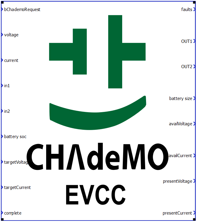
CHAdeMO EVCC component
The CHAdeMO EVCC component implements the EV side of the protocol. It is important to specify that the component implements only the communication interface and not the controller itself. In other words, the component is used only to relay the necessary messages between the EVCC and SECC. The controller (or logic) part is left to the user to implement using Signal Processing components.
The CHAdeMO EVCC component is shown in Table 1.
| component | component dialog window | properties |
|---|---|---|
 |
 |
|
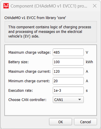
Component parameters are explained in Table 2
| Name | Property name | Default value | Description |
|---|---|---|---|
| Maximum charge voltage | MaxChargeVoltage | 0 | Define the maximum voltage supported by the EV. This is related to the number of cells in series of the battery. |
| Battery size | PackSizeKWH | 0 | Define the EV battery capacity in kWh. |
| Maximum charge current | AskingAmps | 0 | Maximum current allowed during charging of the EV battery. |
| Minimum charge current | MinChargeAmperage | 0 | Minimum current allowed during charging of the EV battery. |
| Execution rate | excRate | 0 | Execution rate of the CHAdeMO component. It is recommended to use 1 millisecond (1e-3). |
| Choose CAN controller | CANcontroller | CAN1 | CAN controller on which the CHAdeMO messages will be executed. |
Input/Output terminals and State values
The Signal Processing signals are passed to and from the CHAdeMO component using its terminals.
Not all values are acceptable and correct for all terminals. Some of them use integer values, some real, and some states. Table 3 explains how each terminal is intended to be used.
| Name | Description | Value type |
|---|---|---|
| bChademoRequest | Defines if CHAdeMO requests are going to be sent to the Charger (1) or not (0) | state (0,1) |
| Voltage | EV battery actual voltage [V] | real |
| Current | Measured charging current | real |
| IN1 | CP control pilot signal detection | unsigned int |
| IN2 | CP2 control pilot signal detection | unsigned int |
| Battery SoC | Battery state of charge [%] | real (0 - 100) |
| targetVoltage | Desired voltage reference to charge the EV battery, as requested by the EVCC to the SECC [V] | real |
| targetCurrent | Desired current reference to charge the EV battery, as requested by the EVCC to the SECC [A] | real |
| complete | Defines the charging session as complete by setting ChargeComplete to 0 (not complete) or 1 (complete) | state (0,1) |
| faults | Defines if the EV is in error state (1) or not (0) | state (0,1) |
| OUT1 | Defines if the Control Pilot CP3 is controlled by the K contactor (1) or not (0) | state (0,1) |
| OUT2 | Defines if the EV contactor should enable charging (1) or not (0) | state (0,1) |
| battery size | State of charge for fully charged battery [%] | real (0 - 100) |
| availVoltage | Maximum voltage accepted by the EVSE [V] | real |
| availCurrent | Maximum current accepted by the EVSE [A] | real |
| presentVoltage | Voltage present in the EVSE DC contacts [V] | real |
| presentCurrent | Current measured by the EVSE [A] | real |
CHAdeMO EVCC component basic logic
The CHAdeMO communication protocol consists of five CAN messages, with three messages dedicated to the vehicle side and two messages for the charging station. These messages are implemented within the Typhoon HIL Control Center software.
Both the charging station and the vehicle have one CAN message each for charge parameters and reporting errors during the charging process. Additionally, the vehicle has a CAN message that expresses the calculated charge time and the state of charge. The project utilizes the CAN 2.0A standard. CAN bus messages have a maximum length of 8 data bytes.
The execution loop is implemented within the C Function block, utilizing the C/C++ programming language. This block also allows for importing C++ files (.cpp) and header files (.h). The inputs to this block consist of received messages from the charger to the EV, along with auxiliary variables. The outputs from this block consist of messages sent by the EV to the charger, as well as additional variables monitored during simulation to ensure proper functioning.
The main function inside the CHAdeMO component checks the received messages over CAN bus and sets the parameters that need to be sent. It also monitors and verifies the values of various parameters, both received and to be sent. Based on these values, the relationship between the electric vehicle and the charging station transitions between different states, such as WAIT_FOR_EVSE_PARAMS and RUNNING (charging process), is defined.
Virtual HIL support
Virtual HIL currently does not support this protocol. When using a non-real-time environment (e.g. when running the model on a local computer), inputs to this component will be discarded and outputs from this component will be zeroed.
References
- International Electrotechnical Commission (IEC), "IEC 61851, Electric vehicle conductive charging system - Part 1: General requirements", 2010, pp. 14
- International Electrotechnical Commission (IEC), "IEC 61851, Electric vehicle conductive charging system - Part 23: DC electric vehicle charging station", 2014, pp. 33-70