Three Phase Two Winding Phase-shifting Transformer
Description of the Three Phase Two Winding Phase-shifting Transformer component in Schematic Editor
Component description

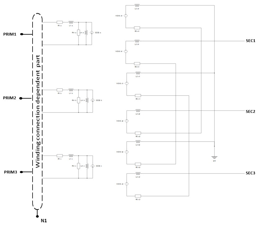
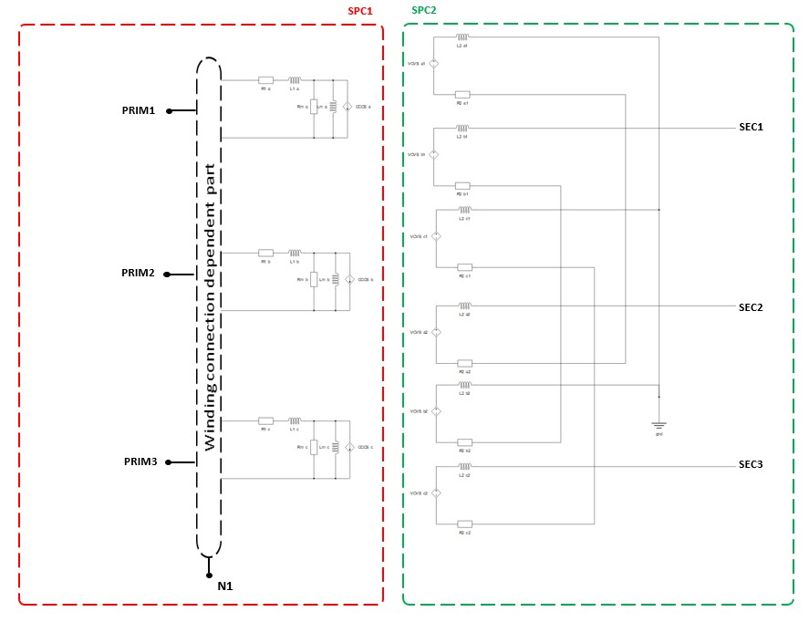
The Three Phase Two Winding Phase-shifting Transformer is modeled as three Single Phase Three Winding Transformers, where the secondary winding of each single-phase transformer is connected to appropriate tertiary winding of the following single-phase transformer.
The magnetization inductance (Lm) is modeled on the primary side of the transformer and can be either linear or with saturation. Core losses are modeled as Rm resistance located on the primary side of the transformer.
A schematic block diagram of the Three Phase Two Winding Phase-shifting Transformer block with the corresponding component arrangement and naming is shown in Figure 2.
It should be noted that terminal N1 can be connected with the rest of the circuit in Schematic Editor only if the corresponding side is wye (Y) connected.

Embedded coupling
Ideal Transformer Embedded coupling type is ignored in TyphoonSim and will not affect TyphoonSim simulation at all.

Ports
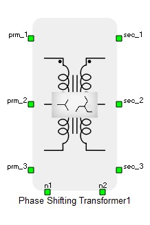
- prm_1 (electrical)
- Primary winding port 1.
- prm_2 (electrical)
- Primary winding port 2.
- prm_3 (electrical)
- Primary winding port 3.
- n1 (electrical)
- Primary winding neutral port.
- sec_1 (electrical)
- Secondary winding port 1.
- sec_2 (electrical)
- Secondary winding port 2.
- sec_3 (electrical)
- Secondary winding port 3.
- n2 (electrical)
- Secondary winding neutral port .
General (Tab)
- Input parameters
- Specifies parameters format (SI, pu, or SC and OC tests).
- Core model
- Selects transformer core model implementation.
- Several levels of model fidelity are available - linear, non-linear, or Rm/Lm neglected.
- Sn
- Nominal Power of the transformer [VA].
- f
- Nominal frequency [Hz].
- V1
- Rated line to line voltage of primary winding [Vrms].
- V2
- Rated line to line voltage of secondary winding [Vrms].
- phase shift
- Angle between primary and secondary line to line voltage. The available values for phase shift range from -180 to 180 [deg].
- r1
- Available if Input parameters is set to pu.
- Resistance of primary winding [p.u.].
- R1
- Available if Input parameters is set to SI.
- Resistance of primary winding [Ω].
- l1
- Available if Input parameters is set to pu.
- Leakage inductance of primary winding [pu].
- L1
- Available if Input parameters is set to SI.
- Leakage inductance of primary winding [H].
- r2
- Available if Input parameters is set to pu.
- Resistance of secondary winding [pu].
- R2
- Available if Input parameters is set to SI.
- Resistance of secondary winding [Ω].
- l2
- Available if Input parameters is set to pu.
- Leakage inductance of secondary winding [pu].
- L2
- Available if Input parameters is set to SI.
- Leakage inductance of secondary winding [H].
- rm
- Available if Input parameters is set to pu and Core model is set to Linear or Non-Linear.
- Resistance representing core losses [pu].
- Rm
- Available if Input parameters is set to SI and Core model is set to Linear or Non-Linear.
- Resistance representing core losses [Ω].
- lm
- Available if Input parameters is set to pu and Core model is set to Linear.
- Magnetization inductance [pu].
- Lm
- Available if Input parameters is set to SI and Core model is set to Linear.
- Magnetization inductance [H].
- Flux values
- Available if Core model is set to Non-Linear.
- List of magnetic flux values [Wb] or [pu].
- Current values
- Available if Core model is set to Non-Linear.
- List of current values [A] or [pu].
- usc1
- Available if Input parameters is set to SC and OC tests.
- Positive sequence short circuit voltage [%].
- Psc1
- Available if Input parameters is set to SC and OC tests.
- Positive sequence short circuit losses [W].
- ioc1
- Available if Input parameters is set to SC and OC tests and Core model is set to Linear or Non-Linear.
- Positive sequence no load excitation current [%].
- Poc1
- Available if Input parameters is set to SC and OC tests and Core model is set to Linear or Non-Linear.
- Positive sequence no load losses [W].
Coupling (Tab)
- Embedded coupling
- Embedded coupling option - divides primary and secondary winding of the Phase-shifting Transformer into separate cores - can be set to Ideal Transformer or None.
Ideal Transformer Embedded coupling type is ignored in TyphoonSim and will not affect TyphoonSim simulation at all.
- Type of coupling element
- Available when Embedded coupling is set to Ideal Transformer.
- Defines whether the inserted coupling element is a core or a device coupling (device coupling is available for all HIL devices except HIL402).
Ideal Transformer Embedded coupling type is ignored in TyphoonSim and will not affect TyphoonSim simulation at all.
Winding connection (Tab)
- Primary winding connection
- Available Y and D connections.