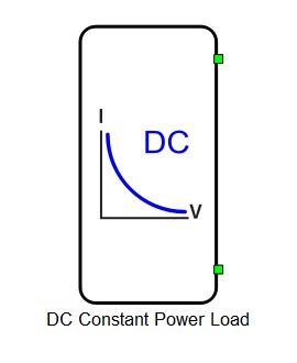
DC Constant Power Load
Description of the DC Constant Power Load/Source component in Schematic Editor

The DC Constant Power Load component is capable of acting as either a DC load or source with current saturation capability.
This component can be controlled from either HIL SCADA or from signal processing logic, by selecting Signal input as Control Method.
Ports
- Port1 (electrical)
- DC+ port.
- Port2 (electrical)
- DC- port.
- Pref (signal processing)
- Available if Control Method is set to Signal input.
- Signal input for providing power setpoints.
General (Tab)
- Current Limit
- Defines the value at which the output current will saturate.
- Control Method
-
There are two control methods avaliable: SCADA input and Signal input.
- When the SCADA input method is selected, the power setpoint is provided via a built-in SCADA input (Pref). If this control method is selected, it is possible to specify on which CPU the signal processing in the component will be executed.
- When the Signal input option is selected, power setpoints are provided through signal input port.
-
- CPU core
- Available if Control Method is set to SCADA input.
- Specifies on which CPU the signal processing in the component will be executed.
- If either option 1 or 2 is selected, signal processing will be executed on the selected core of the User CPU. If System is selected, signal processing code in the component will be mapped to the System CPU.
- Execution rate
- The signal processing time step for calculating output current value.
Snubber (Tab)
- Rsnb
- Snubber resistance.
Since DC Constant power loads/sources are modeled as current sources, it is a good practice to add large resistances in parallel in order to avoid topological conflicts in the circuit. An example where this snubber resistance is required is when the contactor is directly connected to the power source. Without snubber resistances, the contactor switches cannot be opened as there must be a path for the current from the current source(s).
Internal analog measurements to the DC Constant Power Load
| Analog output variable name | Description |
|---|---|
| name_I | Current of DC Constant Power Load |
| name_V | Voltage of DC Constant Power Load |
Extras (Tab)
- Public - Components marked as public expose their signals on all levels.
- Protected - Components marked as protected will hide their signals to components outside of their first locked parent component.
- Inherit - Components marked as inherit will take the nearest parent 'signal_access' property value that is set to a value other than inherit.