Controlled sources
Description of the Controlled Sources components in Schematic Editor.
Six types of controlled sources are available:
Current/Voltage Controlled Sources
Controlled sources can be controlled by any voltage or current from the model. The number of controlled sources used in the model is not limited.
In real-time/VHIL, the only limitation is that the controlled sources must be compiled into the same SPC as the components that control it. Controlled sources are supported for all hardware platforms.


- p_node
- Positive node
- n_node
- Negative node
- Choose signal
 Choose signal is not
supported in TyphoonSim.
Choose signal is not
supported in TyphoonSim.- If enabled, the Control label property will let you choose an appropriate signal from the list of available signals in your model, and that current or voltage will control the controlled source.
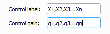
- Control label
- Defines a vector of component labels whose current or voltage will control the controlled source.
- If the Choose signal property is enabled:
- Control label property will let you choose an appropriate signal from the list of available signals in your model, and that current or voltage will control the controlled source.
- Control gain
- Defines the gain of the control value.
- Must be vector of exactly the same length as Control label parameters
- If the Choose signal property is enabled:
- Must be a real number, not a vector.
The output of the controlled source when the Choose signal checkbox is unchecked (Figure 5) can be calculated with the equation:
where Y(t) is the voltage or current output (depending on the type of the source), X1(t)... Xn(t) are the variables defined by the Control label vector of length "n", and g1...gn are the corresponding gain values defined in the Control gain vector. All gain values must be real numbers.
In real-time/VHIL, depending on the component, either current or voltage measurement is enabled by default, which means that a voltage or current of the source will be in the list of analog signals. Measurement can be disabled by setting the Measurement enable parameter to False. This option is useful in situations with large models, where reducing the number of measurements may allow the model to run on a specified HW platform.
- Public - Components marked as public expose their signals on all levels.
- Protected - Components marked as protected will hide their signals to components outside of their first locked parent component.
- Inherit - Components marked as inherit will take the nearest parent 'signal_access' property value that is set to a value other than inherit.
Look-up table controlled sources
In the Component Properties dialog, there are three parameters. Input vector is an array of input values used to calculate the output of the look-up table. Voltage (Current) vector is an array of output values according to the related input values used to calculate the output of the look-up table, and thus the voltage or current of the source. The Control component property is a fully qualified name of a current or voltage measurement that is representing the input to the look up table. The Preview button displays the look-up table function.
In real-time/VHIL simulations, Look-Up-Table Controlled Sources use a hardware based LUT unit implemented in the FPGA of HIL devices.
- p_node
- Positive node
- n_node
- Negative node
- Input vector
- Defines vector of input values.
- Current/Voltage vector
- Defines vector of current/voltage values.
- Control component
- Defines the fully qualified name of the measurement that is representing the input in the look-up table.
Controlled Sources Example
An example schematic diagram that uses controlled sources can be found in the Example Explorer under \how-to examples\controlled sources\ControlledSources.tse.