Photovoltaic panel
Description of the Photovoltaic Panel component in Schematic Editor (t-tn002 - PV module-modeling and application)
Photovoltaic panel model
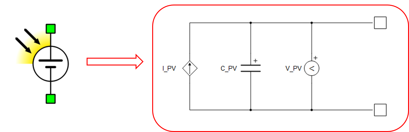
The photovoltaic panel element is modeled as a voltage-controlled current source I_PV with module capacitance C_PV connected in parallel, as shown in Figure 1. The current source I_PV is controlled by the voltage V_PV across the PV panel, in combination with a predefined PV model I-V curve.
The voltage-controlled current source I_PV represents a nonlinear resistor with the I-V characteristics equivalent to the standard PV cell characteristics, often modeled with the equivalent circuit given in Figure 2. The standard PV cell equivalent circuit model comprises an ideal semiconductor p-n junction, a current source that models irradiance flux, and series and shunt resistance that capture internal series and shunt losses.

The PV cell IV curve is given as:
where m is an ideality factor (usually in the range of 1 to 2, with m =1 being ideal), k is the Boltzmann constant, e is the electron charge, and Tc is the junction temperature. The PV module is modeled as a compound parameterized PV cell, comprising an array of individual PV cells connected in series and/or parallel. Hence, a full module, or even a series of modules, is represented with a single PV panel element in Schematic Editor.
Photovoltaic panel component in Typhoon HIL Schematic Editor
| component | component dialog window | component parameters |
|---|---|---|
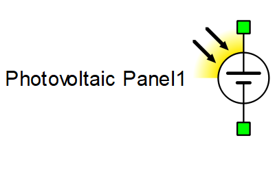 Photovoltaic panel |
 |
Property tabs: |
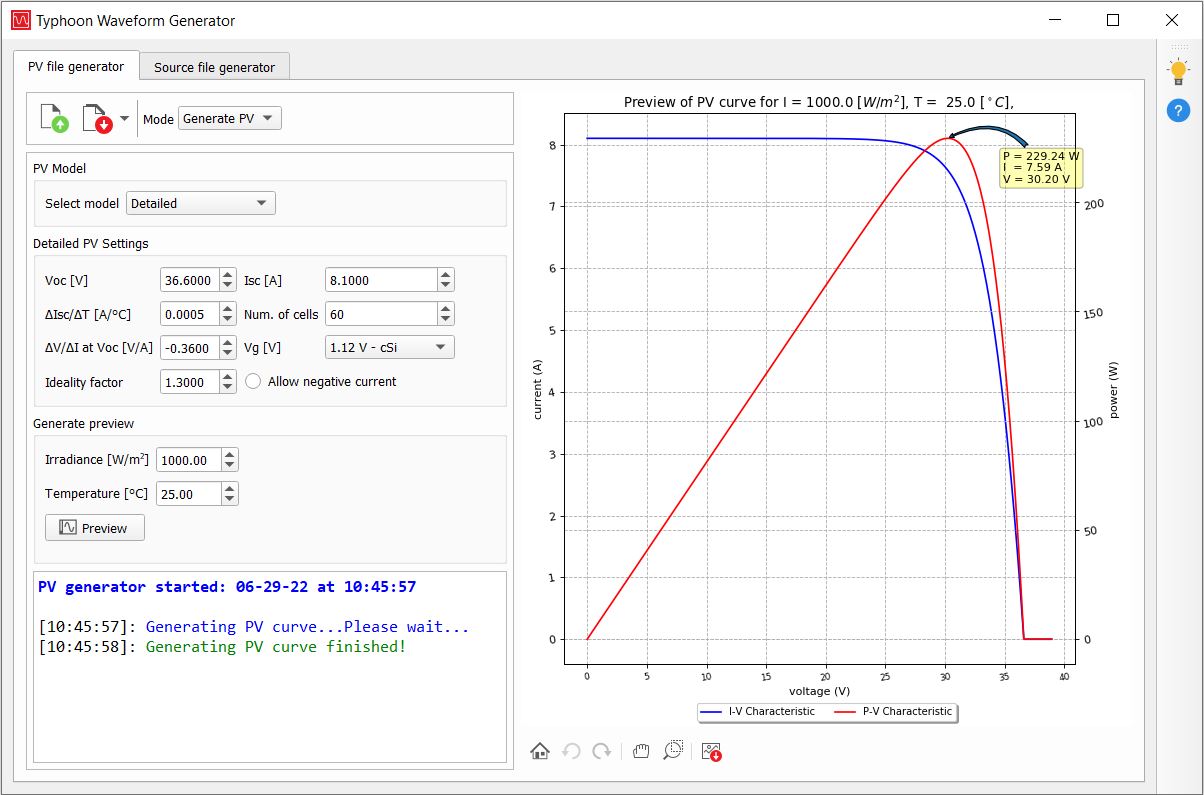
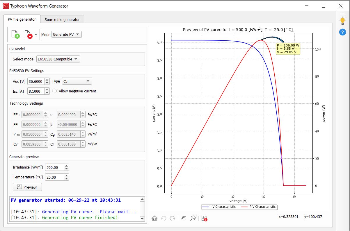
Generating I-V curves in the Typhoon HIL Waveform Generator
- Detailed
- EN50530 Compatible
- Normalized IV
- Voc - open circuit voltage (*STC)
- Isc - short circuit current (*STC)
- ∆Isc/∆T - temperature coefficient of Isc (standard product parameter)
- Number of cells (standard product parameter)
- ∆V/VI at Voc - slope of the U/I characteristic at Voc operating point (product U/I curve)
- p-n junction voltage gap (1.12 for Xtal; 1.75 for amorphous Si)
- Ideality factor - a measure of how closely the diode follow the ideal diode equation (m in the range of 1 to 2)
The preview curve will be displayed for the entered irradiance and temperature.
- Voc - open circuit voltage (*STC)
- Isc - short circuit current (*STC)
- Type - type of the PV panel (cSi, thin film, or user defined)
- FFu - voltage fill factor, ratio of voltage at maximum power point (*STC) to open circuit voltage (*STC)
- FFi - current fill factor, ratio of current at maximum power point (*STC) to short circuit current (*STC)
- α - temperature coefficient of the current
- β - temperature coefficient of the voltage
- Cv, Cr, Cg - technology depending correction factors
The IV curve is a function of irradiance G, and temperature T. In particular, the parameters Isc(STC) and Voc(STC) are obtained under standard test conditions (G(STC)= 1000 W/m2, T(STC)= 25°C). The relationship between the current I and the terminal voltage V of a PV panel parametrized with FFu, FFi, α, β, Cv, Cr and Cg parameters, is given as:
where:
Isc is the short circuit current:
,
Voc is the open circuit voltage:
,
I0 is the reverse diode saturation current:
,
and Caq is a parameter dependent on voltage and current fill factors:
.
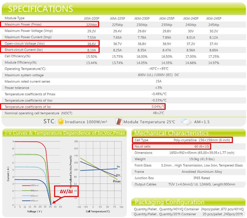
Example: JKM220P-60
This section gives an example of reading the parameters needed for the Waveform Generator tool from a PV module datasheet given in Figure 5.
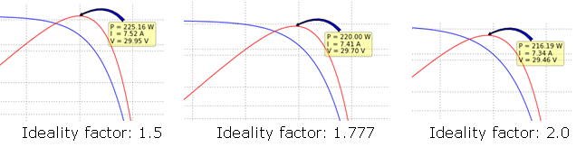
The next steps describe how to determine the ideality factor for a given PV panel. It cannot be read directly from the datasheet, rather it has to be determined experimentally. After entering all the available parameters from the datasheet to the Waveform Generator, an initial value for the ideality factor should be chosen. A good initial guess for crystalline silicon is around 2, while for amorphous silicon is less than 2. Finally, the maximum power displayed on the graph in the Waveform Generator should be compared to the maximum power provided in the datasheet. This process should be repeated until a close enough match between the maximum powers from the PV curve preview and the datasheet is obtained. PV curves for several ideality factors are shown in Figure 6.
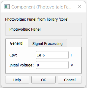
Tab: General
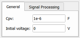
- Cpv
- PV diode capacitance. [F]
- Initial voltage
- Initial voltage of the component. [V]
Tab: Signal Processing
If the option Enable SP-based implementation is checked, the PV panel is modelled using a signal processing based PV model. In this case, the IV curve is simulated at the execution rate of the signal processing components, defined by the Execution rate property. Conversely, if this option is unchecked, the IV curve is simulated at the basic simulation timestep defined in the circuit solver settings. In both cases, the component can be controlled through dedicated HIL API functions.
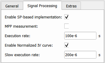
- Enable SP-based implementation
- If checked, enables IV curve definition using the EN50530 compatible PV model.
- MPP measurement
- Enables/disables monitoring of maximum power point (MPP). This property is available if the Enable SP-based implementation checkbox is marked.
- Execution rate
- Type in the desired signal processing execution rate. This value must be compatible with other signal processing components of the same circuit: the value must be a multiple of the fastest execution rate in the circuit. There can be up to four different execution rates, but they must all be multiple of the basic simulation timestep. To specify the execution rate, you can use either decimal (e.g. 0.001) or exponential values (e.g. 1e-3) in seconds. Alternatively, you can type in ‘inherit’ in which case the component will be assigned execution rate based on the execution rate of the components it is receiving input from.
- This property is available if the Enable SP-based implementation checkbox is marked.
- Enable Normalized IV curve
- If checked, enables the IV curve definition using the Normalized IV PV model, in addition to the EN50530 compatible PV model.
- This property is available if the Enable SP-based implementation checkbox is marked.
- Slow execution rate
- Signal processing execution rate at which the Normalized IV curve data points are updated. The slow execution rate applies to the inputs which specify x- and y- data sets, normalizedDataV.value and normalizedDataI.value, respectively. This execution rate, however, does not apply to short circuit current iscSTC and open circuit voltage vocSTC inputs which scale the specified data sets. Instead, these inputs are updated at the faster execution rate, Execution rate.
- This property is available if the Enable SP-based implementation and the Enable Normalized IV curve options are marked.
- CPU core
- Specifies which User CPU core executes the signal processing portion of the component.
- This property is available if the Enable SP-based implementation option is marked, and if the specified HIL device contains multiple User CPU cores to choose from. If the model is compiled for a HIL device which contains only one User CPU core (CPU core 0), then the value of this property is not applied, and the internal signal processing portion is mapped to CPU core 0.
Measurements and inputs internal to the PV component
Available internal measurements are given in Table 2.
| Analog output variable name | Description |
|---|---|
| C1 | Voltage across the PV panel. [V] |
The optional maximum power point (MPP) measurements, illumination, temperature, short circuit current, and open circuit voltage measurements of the signal processing based PV model are available through probes inside the component. These outputs are given in Table 3.
| Analog output variable name | Description |
|---|---|
| Imp | Current at the maximum power point. [A] |
| Vmp | Voltage at the maximum power point. [V] |
| MPP | Power at the maximum power point. [W] |
| illuminationActual | Illumination of the PV Panel, which equals the calculated value in case the illumination reference is delayed using ramping and/or scheduling. [W/m2] |
| temperatureActual | Temperature of the PV Panel, which equals the calculated value in case the temperature reference is delayed using ramping and/or scheduling. [°C] |
| iscActual | Short circuit current of the PV Panel, which equals the calculated value in case the short circuit current reference is delayed using ramping and/or scheduling. [A] |
| vocActual | Open circuit voltage of the PV Panel, which equals the calculated value in case the open circuit voltage reference is delayed using ramping and/or scheduling. [V] |
The references for the signal processing based PV model are provided through SCADA inputs located inside the component. An overview of the available inputs related only to the EN50530 compatible PV model type is given in Table 4.
| Input | Description |
|---|---|
| illumination | An analog input that sets the illumination reference. [W/m2] |
| temperature | An analog input that sets the temperature reference. [°C] |
| FFu | An analog input that sets the FFu maximum power point to the open circuit voltage (technology dependent) ratio. |
| FFi | An analog input that sets the FFi maximum power point to the short circuit current (technology dependent) ratio. |
| Cg | An analog input that sets the Cg (technology dependent) correction factor. [W/m2] |
| Cv | An analog input that sets the Cv (technology dependent) correction factor. |
| Cr | An analog input that sets the Cr (technology dependent) correction factor. [m2/W] |
| Vl2h | An analog input that sets the Vl2h voltage low to high (technology dependent) ratio. |
| alpha | An analog input that sets the α (technology dependent) current temperature coefficient. [%/°C] |
| beta | An analog input that sets the β (technology dependent) voltage temperature coefficient. [%/°C] |
| negCurrent | A digital input that enables negative current if the input value is high. |
| illuminationInitial | An analog input that sets the value of the illumination, which is used as an initial value in case of illumination ramping and/or scheduling at the start of the simulation. [W/m2] |
| temperatureInitial | An analog input that sets the value of the temperature, which is used as an initial value in case of temperature ramping and/or scheduling at the start of the simulation. [°C] |
An overview of the available inputs related only to the Normalized IV PV model type is given in Table 5.
| Input | Description |
|---|---|
| normalizedDataI.value | An analog input that sets the y- data set of the normalized IV curve by specifying the value of its tunable property value. The dimension of the value property is set to 500. |
| normalizedDataV.value | An analog input that sets the x- data set of the normalized IV curve by specifying the value of its tunable property value. The dimension of the value property is set to 500. |
| normalizedDataEnable | A digital input which applies values of normalizedDataI.value and normalizedDataV.value to generate the normalized IV curve if the value of the input is high. If these values are not meant to be applied, for example in case a new pair of x- and y- data sets is set in different simulation time steps, then its value can be set to low. |
An overview of the common inputs is available in Table 6. For the EN50530 compatible PV model type, ramping and/or scheduling can be applied to the temperature, illumination, short circuit current, and open circuit voltage references. For the Normalized IV PV model type, ramping and/or scheduling can be applied to short circuit current and open circuit voltage references.
| Input | Description |
|---|---|
| iscSTC | An analog input that sets the short circuit current at standard operating conditions, if the IV curve is defined using an EN50530 compatible PV model. If the IV curve is defined using a Normalized IV PV model, then the analog input scales the y- data set normalizedDataI.value of the IV curve. [A] |
| vocSTC | An analog input that sets the open circuit voltage at standard operating conditions, if the IV curve is defined using an EN50530 compatible PV model. If the IV curve is defined using a Normalized IV PV model, then the analog input scales the x- data set normalizedDataV.value of the IV curve. [V] |
| iscInitial | An analog input that sets the value of the short circuit current, which is used as an initial value in case of short circuit current ramping and/or scheduling at the start of the simulation. [A] |
| vocInitial | An analog input that sets the value of the open circuit voltage, which is used as an initial value in case of open circuit voltage ramping and/or scheduling at the start of the simulation. [V] |
| pvModelType | An analog input that selects the type of PV model type based on which the IV curve is generated. If its value is 1, the EN50530 compatible PV model is applied. If its value is 2, the Normalized IV PV model is applied. The input is available if both Enable SP-based implementation and Enable Normalized IV curve options are enabled. |
| rampTime | An analog input that sets the duration of the ramping period. [s] |
| executeAt | An analog input that sets the value of the simulation time at which the specified references are applied. Scheduling of multiple simulation times before the first scheduled time has been reached is not supported. [s] |
| rampType | A digital input that determines the shape of the transition of the specified references. If the input value is low, linear transition is applied. If the input value is high, exponential transition is applied. |
| dynamicsEnable | An analog input that disables ramping and/or scheduling if its value is 0, and enables them if its value is 1. Higher values of the analog input are reserved, and are used when ramping and/or scheduling is set using HIL API functions. |
References
[1] Overall efficiency of grid connected photovoltaic inverters, CENELEC, St. EN 50530, 2010