Constant Power Loads/Sources
Description of the Constant Power Loads/Sources components in Schematic Editor
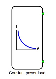
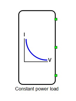
There are two types of constant power loads/sources components: single phase and three phase. The components consist of sine current sources (first harmonic only) which are controlled in a way to achieve a given power flow.
Active and reactive power references are set from HIL SCADA. Positive active power references refer to the load mode, while negative power references refer to the source mode. Constant power load/source components operate in a frequency range from 15 Hz to 100 Hz. Outside that range the sources will turn off.
Single Phase Constant Power Load function
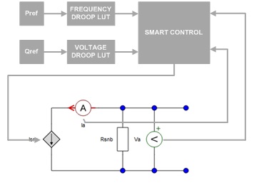
The functional diagram of the Single Phase Constant Power Load is shown in Figure 3. It consists of a controlled current source, meters, an optional snubber resistor, and current control logic. The inputs for the control logic are: reference for active power Pref, processed through the frequency droop look up table; reference for reactive power Qref, processed through the voltage droop look up table; input voltage Va; current value Ia. Droop look up tables are optional and can be enabled if needed.
Three Phase Constant Power Load function
The functional diagram of a Three Phase Constant Power Load is shown in Figure 4. It consists of two controlled current sources, meters, optional snubber resistors, and current control logic. Inputs to the control logic are: reference for active power Pref, processed through the frequency droop look up table; reference for reactive power Qref, processed through the voltage droop look up table; input line-to-line voltage Vab; current value Ia. Droop look up tables are optional and can be enabled if needed.
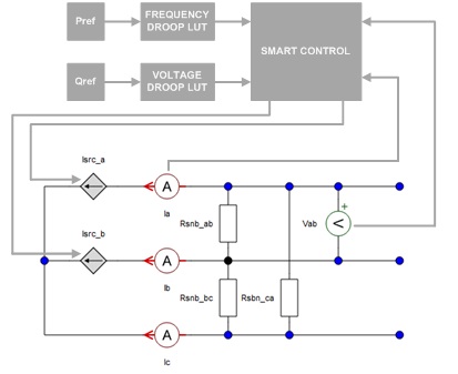
As can be seen in Figure 4, only one of the three currents is measured and only one of the three line-to-line voltages is measured. In other words, it is assumed that the grid is balanced. The Three Phase Constant Power Load will not work as expected if connected to an unbalanced grid.
Ports
- p_node (electrical)
- P port of the Single Phase Constant Power Load.
- n_node (electrical)
- N port of the Single Phase Constant Power Load.
- a_node (electrical)
- A port of the Three Phase Constant Power Load.
- b_node (electrical)
- B port of the Three Phase Constant Power Load.
- c_node (electrical)
- C port of the Three Phase Constant Power Load.
- Pref (in)
- Available if Control Method is set to Signal inputs.
- Signal input for providing active power setpoints.
- Qref (in)
- Available if Control Method is set to Signal inputs.
- Signal input for providing reactive power setpoints.
- frequency (out)
- Available if Control Method is set to Signal inputs.
- Measured frequency.
- locked (out)
- Available if Control Method is set to Signal inputs.
- Internal PLL status.
General (Tab)
- Current Limit
- Defines the RMS value at which the output current will saturate.
- Control Method
-
There are two control methods avaliable: SCADA inputs and Signal inputs.
- When the SCADA inputs method is selected, active and reactive power setpoints are provided via built-in SCADA inputs (Pref and Qref).
- When the Signal inputs option is selected, active and reactive power setpoints are provided through signal input ports. In this mode, the constant power load/source internal PLL status and measured frequency are provided as signal outputs.
-
- Output execution rate
- If Pin to System CPU is checked, the Output execution rate property defines the output execution rate. If Pin to System CPU is unchecked, the output execution rate is the same as Slow execution rate.
- Available if Control Method is set to Signal inputs and Pin to System CPU is checked.
- CPU core
-
If value of the CPU core is System, signal processing code in the component will be mapped to the System CPU. In this case, execution rates for signal processing code inside the component are defined in the Signal processing settings. If the value of CPU core is 0 or 1, signal processing code in the component will be mapped to the chosen CPU. More about this algorithm can be found in the Signal processing settings. In this case, it is possible to specify Slow and Fast execution rates.
-
- Fast execution rate
- Available if Pin to System CPU is unchecked.
- More information about setting execution rates can be found in Execution rates.
- Slow execution rate
- Available if Pin to System CPU is unchecked.
- More information about setting execution rates can be found in Execution rates.
V-F droop (Tab)
- Enable voltage droop
- Enables voltage droop. If enabled, Voltage droop LUT can be specified.
- Voltage droop LUT
- Available if Enable voltage droop is enabled.
- Voltage droop Look Up Table.
- Voltage droop is defined as a Reactive power modulation index that depends on the effective value of an applied voltage.
- Enable frequency droop
- Enables frequency droop. If enabled, Frequency droop LUT can be specified.
- Frequency droop LUT
- Available if Enable frequency droop is enabled.
- Frequency droop Look Up Table.
- Frequency droop is defined as an Active power modulation index that depends on the frequency of an applied voltage.
- Preview
- Available if Enable voltage droop and/or Enable frequency droop is/are enabled.
- Using the preview buttons on the right, the defined droop functions can be seen.
Snubber (Tab)
- Rsnb
- Snubber resistance.
Since Constant power loads/sources are modeled as current sources it is a good practice to add large resistances in parallel in order to avoid degeneration in the circuit. An example where these snubber resistances are required is when the contactor is directly connected to the power source. Without snubber resistances, the contactor switches cannot be opened as there must be a path for the current from the current source(s).
Internal analog measurements to the Single Phase Constant Power Load
| Analog output variable name | Description |
|---|---|
| name_ia | Current of the Single Phase Constant Power Load |
| name_va | Voltage of the Single Phase Constant Power Load |
Internal digital probes to the Single Phase Constant Power Load
| Digital output variable name | Description |
|---|---|
| name_active | Signalizes that the power source is working properly |
Internal analog measurements to the Three Phase Constant Power Load
| Analog output variable name | Description |
|---|---|
| name_ia | Current of phase A of the Three Phase Constant Power Load |
| name_ib | Current of phase B of the Three Phase Constant Power Load |
| name_ic | Current of phase C of the Three Phase Constant Power Load |
| name_vab | Voltage between phase A and B of the Three Phase Constant Power Load |
Internal digital probes of the Three Phase Constant Power Load
| Digital output variable name | Description |
|---|---|
| name_active | Signalizes that the power source is working properly |
Extras (Tab)
- Public - Components marked as public expose their signals on all levels.
- Protected - Components marked as protected will hide their signals to components outside of their first locked parent component.
- Inherit - Components marked as inherit will take the nearest parent 'signal_access' property value that is set to a value other than inherit.