Battery
Description of the Battery component in Schematic Editor
The Battery component is one of several battery components available in Typhoon HIL Schematic Editor. It is a component focused on easy parametrization and representation of multiple battery types, and is often paired with a Battery inverter component. If you need more flexibility in parametrizing your battery, or you would like to represent a more advanced battery model (such as for BMS testing), consider using the newer Battery Cell component instead.
The Battery component is implemented as a controlled voltage source and a series resistance. The voltage source is controlled by a lookup table that is automatically modified by changing the battery type.
In order to get information regarding the battery's state of charge during simulation in HIL SCADA, it is necessary to check the State of charge output (SOC), and to connect the battery to the Probe, which adds the SOC signal (in percentage) to the list of analog signals in HIL SCADA.
In TyphoonSim, the information regarding the battery's state of charge is given by SOC signal (in percentage), which can be observed in TyphoonSim Scope regardless of whether the State of charge output (SOC) is checked or not.
Generic battery model
The battery model is implemented in the Typhoon HIL toolchain using a generic set of equations that describes the behavior of the battery.
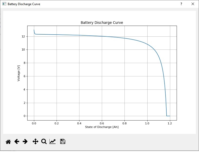
There are 3 points at the battery's discharge curve (Figure 1) that are used by the equations:
- Fully charged battery (Vfull, Q - rated capacity of the battery)
- End of exponential zone (Vexp, Qexp)
- End of nominal zone (Vnom, Qnom)
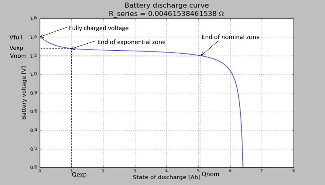
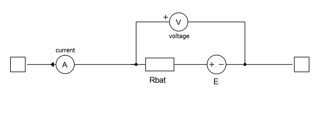
Figure 2 presents a schematic diagram of the battery model. It consists of a controlled voltage source (E) and a series resistance (Rbat). The controlled voltage source is managed by the discharge state of the battery. The battery voltage is a function of the discharge state (it) according to the following formula:
where:
- it: is the discharge state of the battery, defined as:
- A: Voltage drop during the exponential zone:
- 3/B: Charge at the end of exponential zone:
- K: Polarization voltage:
- E0 voltage constant: , where i is the rated discharge current.
The series resistance is calculated by assuming the battery efficiency is 99.5% as follows:
Signal Processing
-
If the State of charge output (SOC) property is enabled, an additional signal processing output port on the battery model will be added (Figure 3), which outputs the current state of charge of the battery. The Execution rate property will be enabled in that case, which determines the execution rate of the signal processing components.
Figure 3. Schematic diagram of the battery model when State of charge output (SOC) property is checked 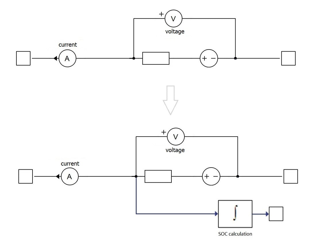
-
If the Use signal processing Look up table property is enabled, the entire battery will be modeled with a Signal Processing lookup table (Figure 4). The initial State of Charge is set in HIL SCADA through the Scada Input property Name.InitialSOC. It can be changed during the simulation runtime. In this case, the Execution rate property will be enabled, adapting the simulation to the execution rate of the signal processing components and not by the time step defined in the circuit solver settings.
Figure 4. Schematic diagram of the battery model when the Signal processing Look up table property is checked 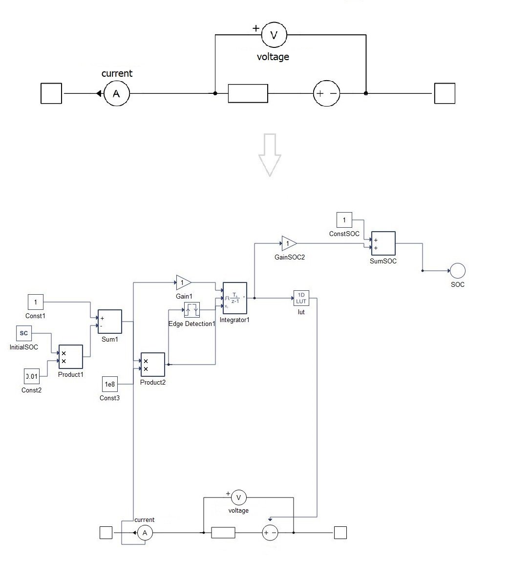
| Variable name | IO Type | Description |
|---|---|---|
| name.current | Analog Output | Battery output current [A] |
| name.voltage | Analog Output | Battery output voltage [V] |
| name.InitialSOC | SCADA Input | Initial state of charge [%] |
Ports
- p node (electrical)
- DC + port.
- n node (electrical)
- DC - port.
- out (out)
- Available if State of charge output (SOC) is enabled
General (Tab)
- Battery type
- Four of the most common battery types are available: Lead-Acid, Lithium-ion, Nickel-Cadmium, and Nickel-Metal-Hydride. If you need additional parameters, you can choose the User defined option for Battery type. This enables additional parameters that allow you to define the battery's SOC curve in detail.
- Nominal voltage
- Nominal voltage of the battery [V]
- Capacity
- Rated capacity of the battery [Ah]
- Initial SOC
- Initial state of charge of the battery [%]
- Full charge voltage
- Available if User defined option for Battery type is selected.
- Percentage of the nominal voltage of battery when it is fully charged (this number is always larger than 100%) [%].
- Nominal discharge current
- Available if User defined option for Battery type is selected.
- Percentage of the rated capacity/1h. [%]
- Internal resistance
- Available if User defined option for Battery type is selected.
- Internal resistance of the battery. [Ω]
- Capacity at nominal voltage
- Available if User defined option for Battery type is selected.
- Percentage of the rated capacity at nominal voltage. [%]
- Capacity at exponential zone
- Available if User defined option for Battery type is selected.
- Percentage of the rated capacity in the exponential zone (see Figure 1) [%]
- Voltage at exponential zone
- Available if User defined option for Battery type is selected.
- Percentage of the nominal voltage in the exponential zone (see Figure 1) [%]
- Preview SOC Curve
-
The Preview SOC Curve button will graph the characteristic SOC curve of a selected battery based on the previous equations (Figure 5).
-
Signal Processing (Tab)
- State of charge output (SOC)
-
Enables an additional signal processing output port on the battery model which outputs the current state of charge of the battery.
-
- Use signal processing Look up table
- Enables modeling of the entire battery with a Signal Processing lookup table
- Execution rate
- The execution rate of the signal processing components
- Available if State of charge output (SOC) and/or Use signal processing Look up table is enabled
- More information about execution rates can be found in Execution rates
Extras (Tab)
- Public - Components marked as public expose their signals on all levels.
- Protected - Components marked as protected will hide their signals to components outside of their first locked parent component.
- Inherit - Components marked as inherit will take the nearest parent 'signal_access' property value that is set to a value other than inherit.