Sum
Description of the Sum component in Schematic Editor, which outputs the sum of the input values
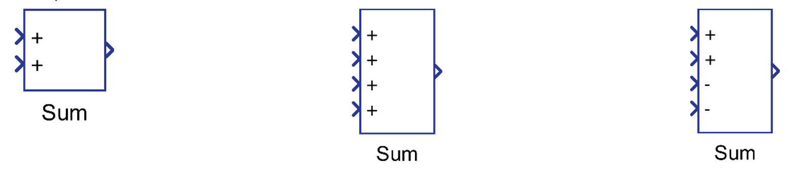
Component Icon
Description
The Sum component outputs the sum of the input values.
If the input is connected to the – input, its sign will be changed (ex. 2 becomes -2), if the input is connected to +, the value stays unchanged.
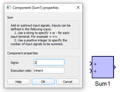
The number of inputs of the sum component is defined using Signs property. If it is defined by integer N, then the block will have N inputs, and all inputs will be +, as it is shown in Figure 2.
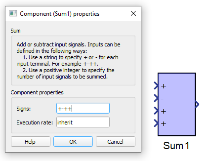
If some of the values are intended to be subtracted, then a string containing characters “+” and “-” for addition and subtraction, must be set on Signs property as illustrated in Figure below.
- If there is one terminal and scalar value on input, the input value will be passed to the output (Example 1).
- If there is one terminal and vector value on input, vector addition will be performed. The output will be scalar (Example 2).
- If there are multiple terminals and all inputs are scalar, the sum value will be determined by adding all the inputs. The output will be scalar. (Example 3).
- If there are multiple terminals and all inputs are vectors, the output will be vector and output value is determined by adding values element-wise. All input vectors must be the same length (Example 4).
- If some inputs are scalars and some vectors, the output will be vector and value will be determined by adding inputs element-wise (if vector) and using scalar values (if scalar). (Example 5).
| in 1 | in 2 | out | |
| Example 1 | -2 | - | -2 |
| Example 2 | [4, -3, -1, 7, -6] | - | 1 |
| Example 3 | 5 | 7 | 12 |
| Example 4 | [-1, 3, 6] | [-3, -2, 4] |
out[0] = -1 -3 out[1] = 3 - 2 out[2] = 6 + 4 out = [-4, 1, 10] |
| Example 5 | 4 | [2, -4, 5] |
out[0] = 4 + 2 out[1] = 4 - 4 out[2] = 4 + 5 out = [6, 0, 9] |
Ports
- Input (in)
-
The input signal to be added or subtracted.
When dealing with vector operation, the size of vectors must be taken into consideration, as sum component can perform element-wise addition or subtraction, the vectors must be the same size.
- Supported types: uint, int and real.
- Vector support: yes.
-
- Output (out)
-
Result of operation performed by the sum component.
When dealing with uint type signals, underflow may occur. If an underflow occurs, the sum component outputs a very large value because of the uint nature of the signal.
- Supported types: uint, int and real.
- The output type is inherited from the input signal.
- Vector support: yes.
- The vector length is calculated based on the number of inputs and input size. If the number of inputs is 1, the output will be scalar. If the number of inputs is larger than 1, the output will be scalar if all inputs are scalar, and vector if any input is vector.
- Supported types: uint, int and real.
-
Properties
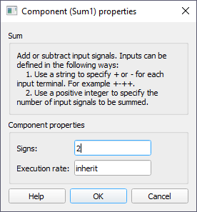
- Signs
- Type in a combination of characters that will define the number of input terminals. If the value is positive integer N, N “+” terminals will be created. If the value is a string containing “+” and “-“ characters, the number of terminals will be the same as the number of characters.
- Execution rate
- Type in the desired signal processing execution rate. This value must be compatible with other signal processing components of the same circuit: the value must be a multiple of the fastest execution rate in the circuit. There can be up to four different execution rates. To specify the execution rate, you can use either decimal (e.g. 0.001) or exponential values (e.g. 1e-3) in seconds. Alternatively, you can type in ‘inherit’ in which case the component will be assigned execution rate based on the execution rate of the components it is receiving input from.