SMBus protocol
Description of the SMBus protocol and its implementation in the Typhoon HIL toolchain.
SMBus Protocol introduction
The System Management Bus (SMBus) is a synchronous serial communication interface specification used for short-distance communication, primarily in embedded systems.
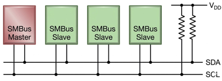
SMBus devices communicate in half-duplex mode using a master-slave architecture usually with a single master. The master (controller) initiates all communication for reading and writing. Multiple slave devices can be connected on the same bus, each identified by a unique 7-bit address. Communication occurs over two lines: SDA (data) and SCL (clock), with open-drain drivers and pull-up resistors.
Interface
The SMBus bus specifies two logic signals:
- SCL: Serial Clock (output from master)
- SDA: Serial Data (bidirectional line for data transfer)
SMBus Commands
SMBus command is a structured message used for communication between devices over the SMBus protocol. It defines how a master device interacts with slave devices using standardized operations. An example of such commands is the Write/Read Word/Byte command, which allows access to a specific register by writing or reading a 16-bit or 8-bit value.
SMBus Write Word Command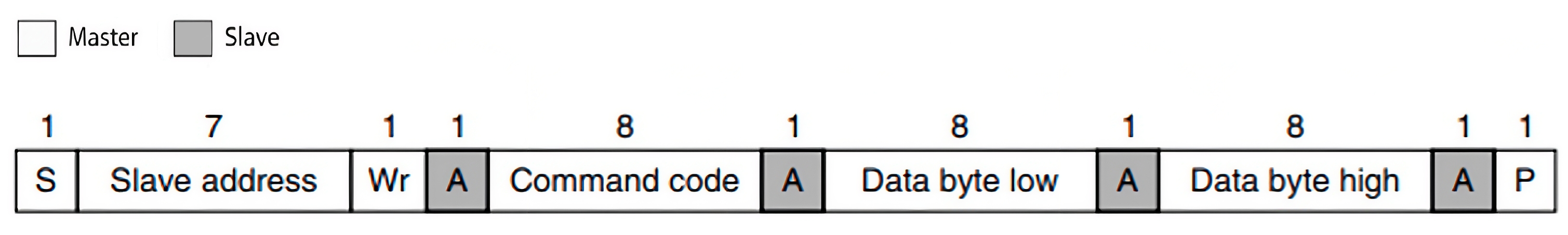
- START condition – Master pulls SDA low while SCL is high.
- Slave Address + Write Bit – 7-bit slave address + 1-bit write flag (0 for write).
- ACK from Slave – Slave acknowledges the address.
- Command Code – Master sends the register/command byte.
- ACK from Slave – Slave acknowledges the register byte.
- Data Byte(s) – Up to two bytes of data are available to write per message.
- ACK after each byte – Slave acknowledges each byte received.
- PEC (optional) – Master may append a Packet Error Code for error checking.
- ACK from Slave (if PEC is included) – Slave acknowledges the PEC byte.
- STOP condition – Master releases SDA while SCL is high.
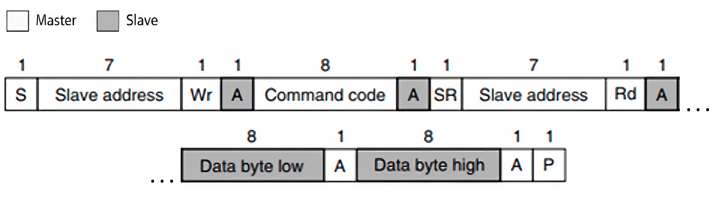
- START condition – Master pulls SDA low while SCL is high.
- Slave Address + Write Bit – 7-bit slave address + 1-bit write flag (0 for write).
- ACK from Slave – Slave pulls SDA low to acknowledge.
- Command / Register Byte – Master sends the register address it wants to read from.
- ACK from Slave – Slave acknowledges the register byte.
- REPEATED START condition – Master initiates another START without releasing the bus.
- Slave Address + Read Bit – Master sends the 7-bit slave address + 1-bit read flag (1 for read).
- ACK from Slave – Slave acknowledges the read request.
- Data Byte(s) from Slave – Slave sends the requested data byte(s).
- ACK after each byte – Master acknowledges each byte received.
-
PEC (optional) – Slave may append a Packet Error Code for error checking.
-
ACK from Master (if PEC is included) – Master acknowledges the PEC byte.
- NACK from Master – After the last byte, the master sends a NACK to signal the end of reading.
- STOP condition – Master releases SDA while SCL is high.
SMBus protocol in Typhoon HIL toolchain
Currently, SMBus Slave functionality in Typhoon HIL is implemented directly on the HIL device (supported by the following Typhoon HIL devices: HIL101, HIL404, HIL506, and HIL606). Only one SMBUS Slave component is supported on schematic per one HIL device.
It is implemented using the GPIO connector. This limits the use of the protocol to the devices that have this type of connector. Information regarding the available ports for each HIL Simulator device is documented in their respective General Specifications section. The pinout for the GPIO connector per HIL device is also detailed there in the Mechanical section.
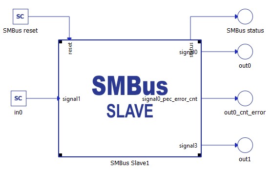
SMBus Slave
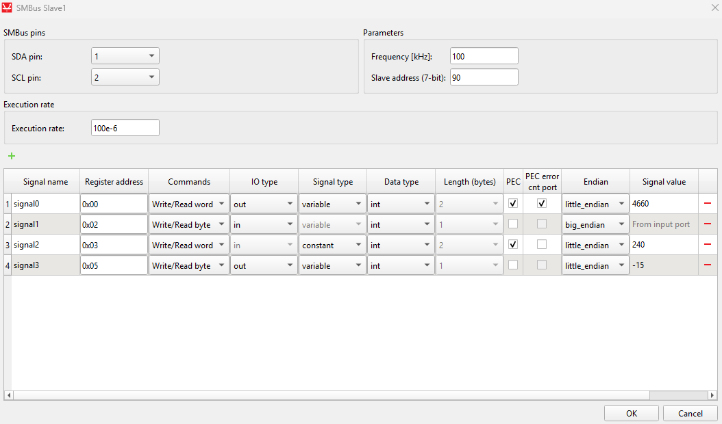
The SMBus Slave component implements the Slave part of the SMBus protocol. This component is used to configure the SMBus Slave operating mode.
- SDA
- Defines which GPIO pin is used for the SDA signal.
- SCL
- Defines which GPIO pin is used for the SCL signal.
- Frequency [kHz]
- Defines the bus frequency that the Slave expects from the Master, which can be in the range of 10 kHz to 100 kHz.
- Slave address [7-bit]
- Defines the unique 7-bit slave address (0 - 127).
- Execution rate
- Signal processing execution rate.
- Register map
- Defines the list of registers on the Slave device.
- Signal name
- Defines the name of the register.
- Register address
- Defines the register address which is used to access register data.
- Commands
- Defines the supported command type:
- Write / Read Word
- Write / Read Byte
- Defines the supported command type:
- IO type
- Available only if Signal type is set to variable.
- Defines whether the register is an input or output.
- Signal type
- Available only if IO type is set to output.
- Defines whether the register is variable or constant.
- Output registers can only be defined as variable.
- Data type
- Defines the type of data that the register holds.
- PEC
- Defines whether the Packet Error Code (PEC) is included in the SMBus frame.
- PEC error cnt port
- Defines the port that outputs the Packet Error Code error count.
- If selected, an additional output port for the PEC error counter is created.
- Length
- Defines the register length:
- 2 bytes if the command is Write / Read Word.
- 1 byte if the command is Write / Read Byte.
- Defines the register length:
- Endian
- Defines the endianness of the register data.
- Signal value
- Defines the initial register value (for output and constant registers).
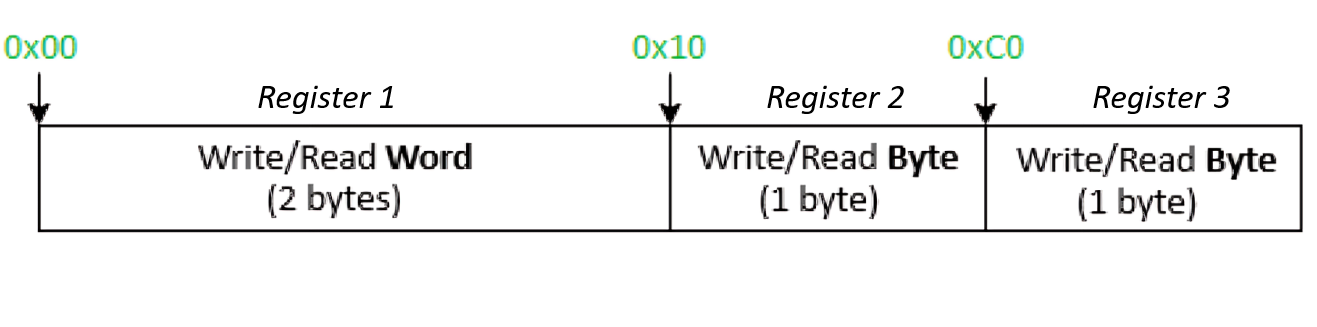
Accessing registers
Register data are accessed using the register byte address as the command code in the SMBus frame sequence. The choice of command code itself determines whether the register is a Word (two-byte) or Byte (one-byte) register, and the associated command type tells the Slave what type of data to expect. An example of this is shown in Figure 4.
SMBus reset
The SMBus Slave application can be disabled by providing a non-zero value to the the reset input while the simulation is running. This will cause the application to reset and stay in a disabled state until a 0 is detected at the reset input. Reseting the SMBus Slave application will clear all active SMBus status codes.
SMBus status
The SMBus status output is used to monitor the SMBus status which can help troubleshoot potential errors. Table 1 contains possible error codes and their descriptions. Each error has dedicated bit value(s) that respresent the error code status.
| Value | Error |
|---|---|
| 8 (0x08) | Receive buffer underflow |
| 4 (0x04) | Transfer buffer overflow |
| 2 (0x02) | Receive buffer overflow |
| 1 (0x01) | Timeout |
SMBus Slave example
This example uses a SCADA Input to set the value of the input register, as well as Probes to read the values of the output registers. The SMBus Slave component is configured as shown in Figure 5.
The registers definition is shown in Figure 6.