IEC 60870 Client
Description of the IEC 60870 Client implementation in the Typhoon HIL toolchain.
IEC 60870-5-104/IEC 104 protocol
IEC 60870-5-104 protocol (IEC 104) is a part of the IEC Telecontrol Equipment and Systems standard IEC 60870-5. It defines a communication profile used for transmitting telecontrol messages between systems in electrical engineering and power system automation. Telecontrol refers to the exchange of supervisory data and control commands used for monitoring and managing power transmission and distribution systems.
IEC 104 extends the IEC 60870-5-101 (IEC 101) protocol by enabling communication over standard TCP/IP networks. In practice, IEC 101 application messages are encapsulated and transmitted over TCP, typically using port 2404. This allows seamless integration of telecontrol systems over Ethernet-based infrastructures.
- The IEC 60870-5-104 Client represents the controlling station (e.g., SCADA system).
- IEC 60870-5-104 Server represents the controlled station (e.g., RTU or substation device).
- Sending control commands to the server (e.g. switching operations, setpoint changes).
- Requesting data from the server (e.g., interrogation, read commands).
- Receiving spontaneous and requested data updates from the server.
- Monitor Direction – Data sent from the controlled station (server/RTU) to the controlling station (client/SCADA), such as measurements and status indications.
- Control Direction – Commands sent from the controlling station (client/SCADA) to the controlled station (server/RTU), such as switching or setpoint commands.
- Reversed Direction – Less common mode where roles are logically inverted.
- Process information (e.g. single point status, mesured values).
- Control commands (e.g., single/double commands, setpoints).
- System information (e.g., interrogation, clock synchronization, reset).
Each message in IEC 104 is carried inside an Application Service Data Unit (ASDU), which contains one or more information objects of the same type. The structure of the ASDU depends on the variable structure qualifier, but the fundamental unit of information exchange is the information element.
- Initiating and maintaining connections to one or more servers.
- Managing command transmission in control direction.
- Handling responses and spontaneous data in monitor direction.
- Coordinating data acquisition through mechanisms such as interrogation and read commands.
IEC 60870 Client component
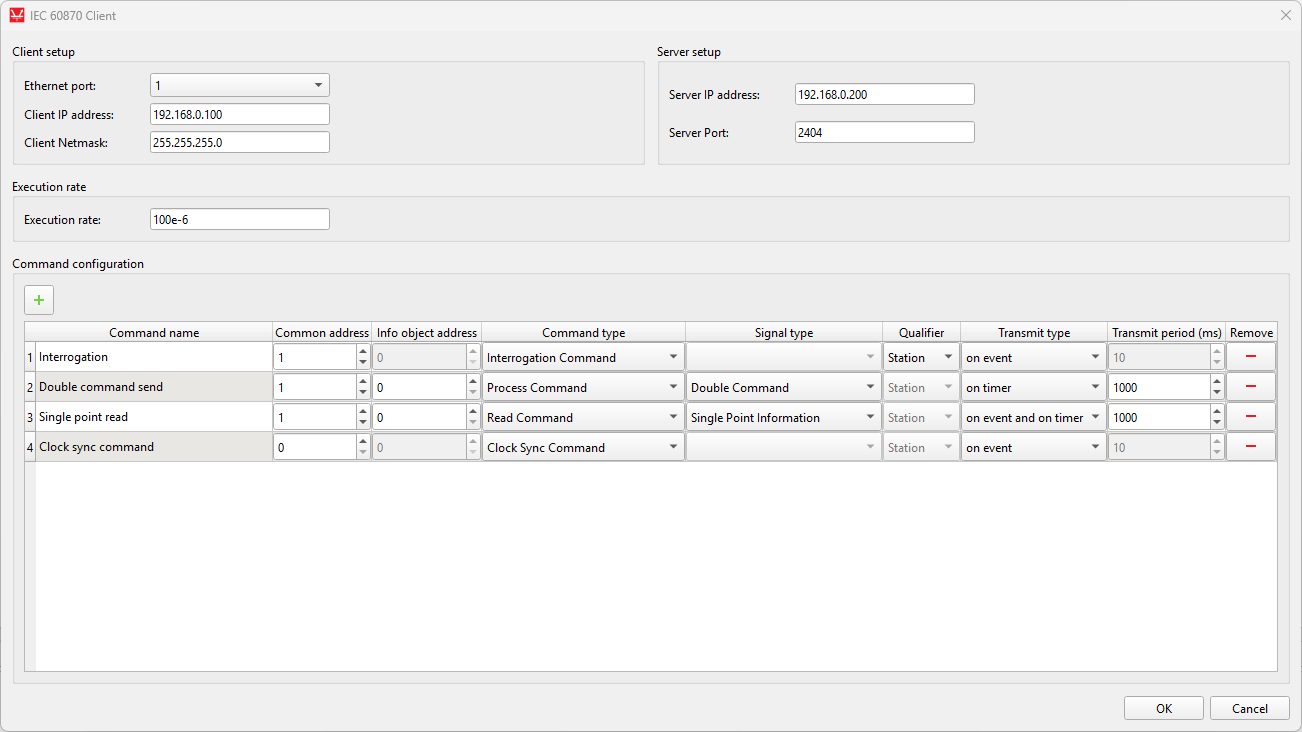
The IEC 60870 Client component is shown in Figure 1.
The IEC 60870 Client, which is available in the Communication library under the IEC 60870 sub-category, implements IEC 60870-5-104 Client functionality and is modeled as a signal processing component. It is supported on the following Typhoon HIL devices: HIL402, HIL101, HIL404, HIL602+, HIL604, HIL506, and HIL606.
- Client setup
- Ethernet port
- Select the Ethernet port on the back of the HIL device used by the IEC 60870 Client application. For 4th generation devices (HIL101, HIL404, HIL506, and HIL606), any available port can be used for communication, while older devices only support communication over port 1.
- Client IP address
- Specify the IEC 60870 Client IP address. The defined IP address will be applied to the HIL Device and it will use the specified address to connect to the IEC 60870 Server.
- Client Netmask
- Specify the netmask of the IEC 60870 Client component.
- Ethernet port
- Server setup
- Server IP address
- Specify the IP address that the IEC 60870 Client will try to connect to.
- Server Port
- Specify the port number that the IEC 60870 Client will try to connect to.
- Server IP address
- Execution rate
- Specify the execution rate of the IEC 60870 Client component.
- Command configuration
- This table is used to define all commands that the Client sends to the Server. Please see the Command configuration section for more information on the configurable parameters.
Command configuration
The Command Configuration table is used to define all commands that the IEC 60870-5-104 Client sends to the Server. Each row represents a single command definition, including addressing, type, and transmission behavior.
- Command name
- This field defines the unique name of the command. It is used to identify the command within the model. The name should be descriptive to clearly indicate the purpose of the command.
- Common address (CA)
- The Common Address specifies the address of the target station (server/RTU). It is used to identify which remote device the command is intended for. This value must match the configured common address on the server side.
- Info object address (IOA)
- The Information Object Address uniquely identifies the data point within the server. Each command is associated with a specific IOA that corresponds to a process variable or control point on the remote device.
- Command type
- This field defines the type of command being sent. Supported command
types include:
- Interrogation Command
- Counter Interrogation Command
- Process Command
- Read Command
- Clock Sync Command
- Test Command
- This field defines the type of command being sent. Supported command
types include:
- Signal type
- The Signal Type defines the specific information object within the selected command type. For example, within Process Commands, this can be Single Command, Double Command, Step Command, or Setpoint commands. This selection determines how the command value is interpreted and encoded.
- Qualifier
- Qualifier provides additional information required by certain command types. Its meaning depends on the selected command. For example, in interrogation commands it defines the interrogation group, while in process commands it may define execution behavior. If not applicable, a default value is used.
- Transmit type
- This field defines how the command is transmitted:
- On event – if selected, additional terminal on the component is created that lets you connect the event signal
- On timer – the command is sent at a fixed time interval
- On event and on timer - if selected, an additional terminal on the component is created that lets you connect the event signal and the command is also sent at a fixed time interval
- This field defines how the command is transmitted:
- Transmit period (ms)
- Lets you define the request sending period (in ms)
An example of request definition is presented below which creates the component connections shown in Figure 3.
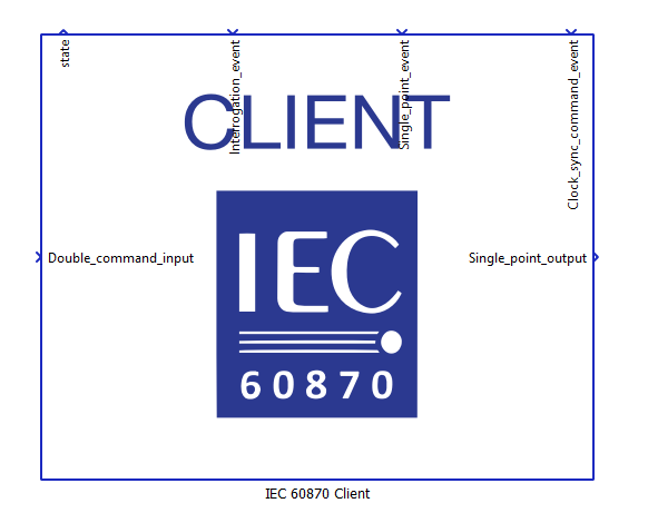
Based on the defined commands, the component dynamically creates input and output terminals depending on the selected command types and their functionality.
For Process Commands, input terminals are created. These terminals are used to send values from the model to the Server. Any value applied to these inputs is encoded into the corresponding IEC 60870 command (e.g., Single, Double, Step, or Setpoint command) and transmitted to the Server according to the configured transmission mode (event-based or periodic).
For Read Commands, output terminals are created. These terminals receive values from the Server and make them available within the model. The Client issues read requests to the Server, and the received values are written to the corresponding output terminals.
For Interrogation Command and Counter Interrogation Command, only event-based input terminals are created. These terminals are used to trigger the transmission of interrogation requests. When an event is detected on the terminal, the Client sends the corresponding interrogation command to the Server. The actual data is not directly mapped to these terminals but is instead received through previously defined Read Commands and written to their associated output terminals.
For Clock Synchronization Command and Test Command, only command triggering is supported. These commands do not create additional data terminals, as they are used solely to send control messages to the Server without expecting direct value mapping to the model.
For commands configured with event-based transmission, additional trigger terminals are created. Any change in the value of these terminals is treated as an event and causes the Client to send the corresponding command immediately.
This design ensures a clear separation between control signals sent to the Server and data received from the Server, while maintaining flexibility in how commands are triggered and processed within the model.
IEC 60870 Client state machine
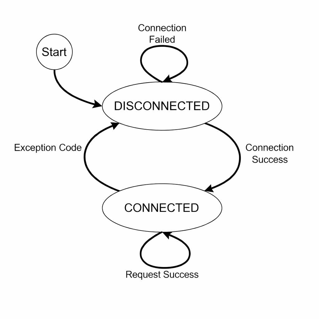
At the beginning of the simulation, the Client is in the DISCONNECTED state. In this state, the Client attempts to establish a connection with the configured Server. If the connection attempt is successful, the Client transitions to the CONNECTED state. If the connection fails, the Client remains in the DISCONNECTED state and continuously retries to connect to the Server.
Once the Client enters the CONNECTED state, it maintains an active communication session with the Server. In this state, the Client can send commands (e.g., process commands, interrogation, read requests) and receive responses or spontaneous data from the Server.
If a connection failure occurs while in the CONNECTED state (e.g., loss of TCP connection or communication timeout), the Client transitions back to the DISCONNECTED state and starts attempting to reconnect to the Server.
The Client continuously cycles between these two states depending on the connection status, ensuring persistent communication with the Server.
Virtual HIL support
Virtual HIL currently does not support this protocol. When using a Virtual HIL environment (e.g. when running the model on a local computer), inputs to this component will be discarded and outputs from this component will be zeroed.