Logical Operator
Description of the Logical Operator components in Schematic Editor, which performs logical operations among all its input signals.
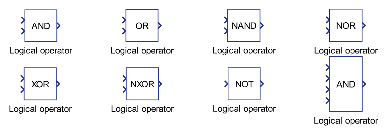
Component Icon
Description
The Logical Operator component performs the chosen logical operation among all the input signals.
The inputs of the component are treated as Boolean values. That is, everything that is not 0 is treated as True and 0 is treated as False.
- AND – out is True if all inputs are True
- OR – out is True if any of the inputs are True
- NAND – inverted AND operation, out is False if all the inputs are True
- NOR – inverted OR operation, out is False if any of the input is True
- XOR – false if all inputs are True or False
- NXOR – inverted XOR operation, True if all inputs are True or False
- NOT – inverted input value
| in1 | in2 | AND | NAND | OR | NOR | XOR | NXOR | NOT(in1) |
| 0 | 0 | 0 | 1 | 0 | 1 | 0 | 1 | 1 |
| 0 | 1 | 0 | 1 | 1 | 0 | 1 | 0 | 1 |
| 1 | 0 | 0 | 1 | 1 | 0 | 1 | 0 | 0 |
| 1 | 1 | 1 | 0 | 1 | 0 | 0 | 1 | 0 |
The number of input terminals is defined by the Number of inputs property for all operators except for NOT. If NOT is selected, only one input terminal can exist on the component.
The inputs can be of the scalar or vector type.
The output is scalar if all inputs are scalar.
If all inputs are vectors, they must be the same length and the output is also a vector.
If all inputs are vectors, they must have the same length and the operation is performed element-wise. The output is a vector with the same length as the inputs.
| in 1 | in 2 | in 3 | operation | Out | |
| Example 1 | 2 | 1 | 0 | AND |
2 and 1 and 0 out = 0 |
| Example 2 | [1, 2] | [2, 1] | [-1, 0] | AND |
out[0] = 1 and 2 and -1 out[1] = 2 and 1 and 0 out = [1, 0] |
| Example 3 | [1, 1] | [2, 1] | 0 | AND |
out[0] = 1 and 2 and 0 out[1] = 2 and 1 and 0 out = [0, 0] |
| Example 4 | [0, 1] | NOT | out = [1, 0] |
Ports
- Input (in)
- Signals to be applied to the logical operator. When the configured
logical operator is NOT, the logical operator component has only one
input port.
- Supported types: uint, int and real.
- Vector support: yes.
- Signals to be applied to the logical operator. When the configured
logical operator is NOT, the logical operator component has only one
input port.
- Output (out)
- Result of the chosen logical operation. The result is 1 for True and 0
for False.
- Supported types: uint, int and real.
- The output type is inherited from the input signal.
- Vector support: yes.
- The vector length is inherited from input signals.
- Supported types: uint, int and real.
- Result of the chosen logical operation. The result is 1 for True and 0
for False.
Properties
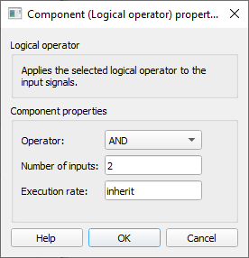
- Operator
- Select the logical operation that will be performed by the component. The available logical operations are: AND, OR, NAND, NOR, XOR, NXOR, and NOT.
- Number of Inputs
- Type in the number of inputs to the component. When NOT is selected, this parameter becomes unavailable as NOT only takes one input
- Execution rate
- Type in the desired signal processing execution rate. This value must be compatible with other signal processing components of the same circuit: the value must be a multiple of the fastest execution rate in the circuit. There can be up to four different execution rates. To specify the execution rate, you can use either decimal (e.g. 0.001) or exponential values (e.g. 1e-3) in seconds. Alternatively, you can type in ‘inherit’ in which case the component will be assigned execution rate based on the execution rate of the components it is receiving input from.