Comparator
Description of the Comparator component in Schematic Editor, which compares two input signals and outputs a binary value
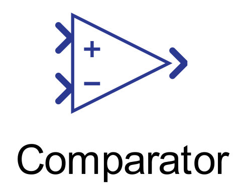
Component Icon
Description
The Comparator component compares two input signals and outputs a binary value.
The function of the Comparator component can be described with the following expression:
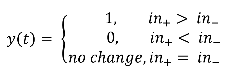
If the non-inverting (+) input is greater than the inverting (–) input, the output will be 1. If the non-inverting (+) input is lower than the inverting (–) input, the output will be 0. If the inputs are equal the output will not change.
Figure 2 below illustrates the functionality of the Comparator component.
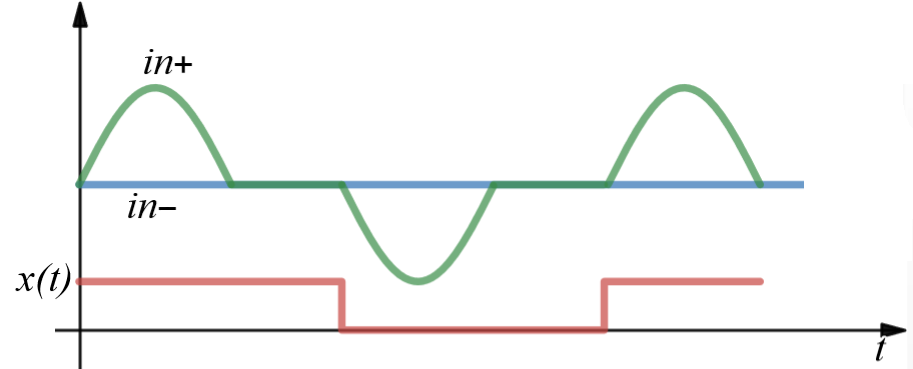
- Initial Value: If both inputs are equal at the beginning of simulation, the output will be 0.
Ports
- + Non inverting input (in)
- Supported types: uint, int and real.
- Vector support: No.
- - Inverting input (in)
- Supported types: uint, int and real.
- Vector support: No.
- Output port (out)
- Supported types: uint, int and real.
- Output type is inherited from the input signals.
- Vector support: No.
- Supported types: uint, int and real.
Properties
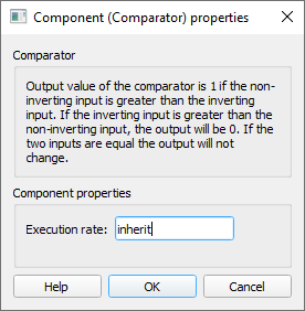
- Execution rate
- Type in the desired signal processing execution rate. This value must be compatible with other signal processing components of the same circuit: the value must be a multiple of the fastest execution rate in the circuit. There can be up to four different execution rates. To specify the execution rate, you can use either decimal (e.g. 0.001) or exponential values (e.g. 1e-3) in seconds. Alternatively, you can type in ‘inherit’ in which case the component will be assigned execution rate based on the execution rate of the components it is receiving input from.