Single-Phase Meter
This section describes the Single-phase Meter component located in the Measurements category of the Schematic Editor core library.
The Single-phase Meter component is part of the fundamental set of measurements available in Schematic Editor. The Single-phase Meter measures Current and Voltage of a single-phase system, and calculates the Active Power, Apparent Power, Reactive Power, RMS Voltage, RMS Current, and power factor. Additionally, the identified frequency and the synchronization signals in the stationary frame (αβ) are provided. Within the properties window of the Single-phase Meter, some parameters can be configured. The Single-phase Meter icon is shown in Figure 1.
User interface
The Single-phase Meter interface allows the user to set the Nominal Frequency (Hz), the number of cycles for averaging RMS values, the component execution rate, and enabling or disabling the signals port.
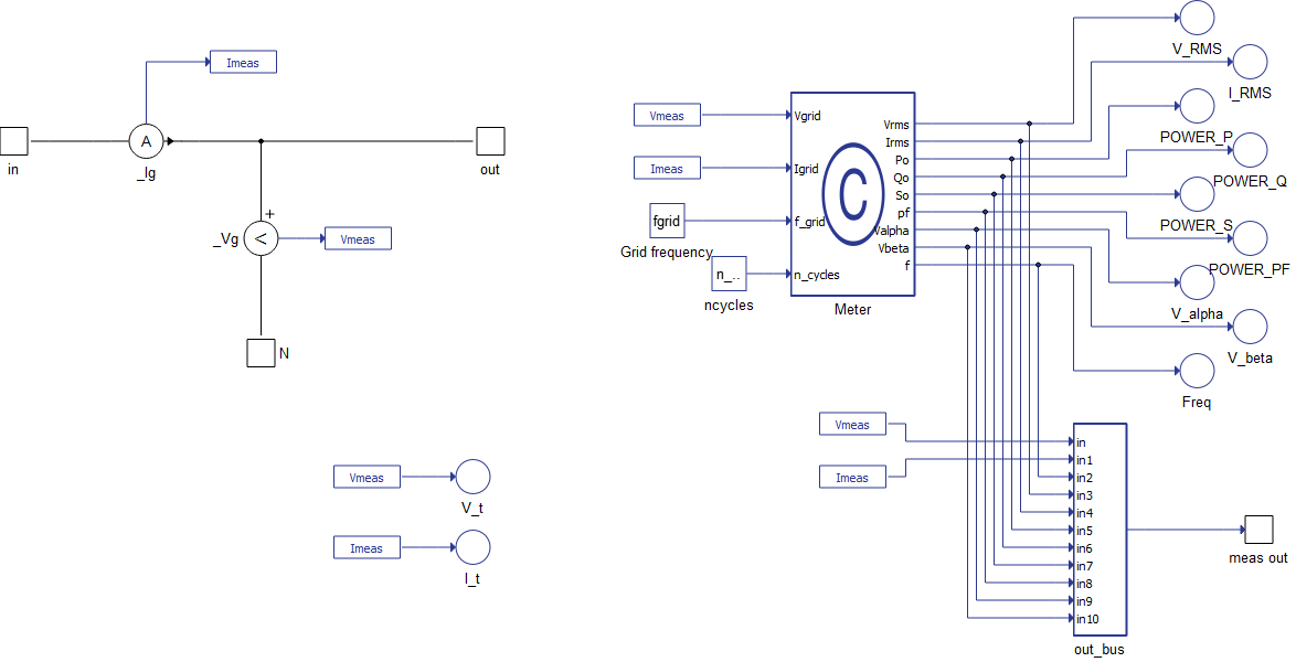
Output signals of the Single-phase Meter component are available through Probes and by an output port. By using this method, all the measurements can be used in the SCADA environment and also in Schematic Editor. When the output port is checked, all signals are also available through the "meas out" port.
To access the signals in Schematic Editor without the output port enabled, use the Signal Picker Source component and select the desired signal of the Single-phase Meter internal probes.
In Figure 2, the internal structure of the component as well the available signals can be seen.
General Characteristics of the Single-phase Meter
The Single-phase Meter uses a Frequency-locked loop (FLL) [1] synchronization algorithm to measure the input signal frequency and perform RMS calculations over each signal period. The Reactive Power is calculated by integrating the instantaneous reactive power, given by Vβ*i(t) [2]. Therefore, some time is required for the algorithm to give stable readings after running the model.
To avoid errors caused by signal aliasing, the Voltage and Current measurements have their bandwidth limit enabled at 1/3 of the frequency of the Single-phase Meter component execution rate.
For example, if the Single-phase Meter component execution rate is set to 100 μs (10 kHz), the bandwidth limit of the Voltage and Current measurements will be automatically set to 1/300e-6 (10/3 kHz).
The parameters "Nominal Frequency" and "Number of cycles for RMS avg" must be set within their limits, or else they will be automatically adjusted during the compilation process.
Ports
- in
- Sinusoidal phase input connection of the single-phase system.
- Supported types: real.
- Vector support: no.
- Sinusoidal phase input connection of the single-phase system.
- out
- Sinusoidal phase output connection of the single-phase system.
- Supported types: real.
- Vector support: no.
- Sinusoidal phase output connection of the single-phase system.
- N
- Sinusoidal Neutral connection of the single-phase system.
- Supported types: real.
- Vector support: no.
- Sinusoidal Neutral connection of the single-phase system.
- meas out (out)
- Vector output containing the measurements (11 signals).
- Supported types: real.
- Vector support: yes.
- The available signals in the meas out port are:
- meas out[0]: Voltage measurement (V_t probe).
- meas out[1]: Current measurement (I_t probe).
- meas out[2]: Frequency of the input signal (Hz) (Freq probe).
- meas out[3]: RMS voltage (V_RMS probe).
- meas out[4]: RMS current (I_RMS probe).
- meas out[5]: Active Power (POWER_P probe).
- meas out[6]: Reactive Power (POWER_Q probe).
- meas out[7]: Apparent Power (POWER_S probe).
- meas out[8]: Power factor (POWER_PF probe).
- meas out[9]: In-phase sin(wt) signal (V_alpha probe).
- meas out[10]: 90º lagged cos(wt) signal (V_beta probe).
- Vector output containing the measurements (11 signals).
Properties
- Nominal Frequency
- Type in the nominal frequency of the input signal, in the range from 30 to 80 Hz.
- Number of cycles for RMS avg
-
An integer value from 1 to 64 to set the number of cycles that are being used to the RMS average calculation.
-
- Execution rate
- Type in the desired signal processing execution rate. This value must be compatible with other signal processing components of the same circuit: the value must be a multiple of the fastest execution rate in the circuit. There can be up to four different execution rates. To specify the execution rate, you can use either decimal (e.g. 0.001) or exponential values (e.g. 1e-3) in seconds. Alternatively, you can type in ‘inherit’ in which case the component will be assigned execution rate based on the execution rate of the components it is receiving input from.
- Enable output port
-
If checked, the measured signals will be available through the "meas out" port, in addition to the internal probes.
-
References
[1] P. Rodriguez, A. Luna, I. Candela, R. Teodorescu and F. Blaabjerg, "Grid synchronization of power converters using multiple second order generalized integrators," 2008 34th Annual Conference of IEEE Industrial Electronics, 2008, pp. 755-760, doi: 10.1109/IECON.2008.4758048.[2] E. Moulin. Measuring Reactive Power in Energy Meters. Metering International - Issue 1 2002, Analog Devices.